


In this article, we will introduce how to connect a soil nitrogen, phosphorus, and potassium (NPK) sensor to an Arduino and build an Arduino soil NPK meter. Using a soil NPK sensor and an Arduino, you can easily measure soil nutrient content. Measuring soil N (nitrogen), P (phosphorus), and K (potassium) content is essential for determining how much nutrient to add to the soil to improve crop fertility.
Soil fertility can be detected using nitrogen, phosphorus, and potassium sensors. The main components of soil fertility are nitrogen, phosphorus, and potassium. Knowledge of soil nutrient concentrations helps us understand nutrient deficiencies or abundances in the soil that supports plant production. Various methods exist for measuring soil nutrient content, such as using optical sensors or spectrometers. However, spectroscopic analysis methods are inconvenient, with a drawback being that the data accuracy is only 60-70%. When comparing spectroscopic analysis methods with traditional wet chemical methods, the accuracy of the products is not yet fully resolved due to the lack of relevant data.
Therefore, in this article, we will use the JXCT soil nitrogen, phosphorus, and potassium sensor to detect the nitrogen, phosphorus, and potassium content in the soil. The JXCT soil nitrogen, phosphorus, and potassium sensor is a low-cost, fast-response, high-precision, and portable sensor that works with the Modbus RS485. Compared to traditional detection methods, this sensor offers the advantage of providing very fast measurements and highly accurate data. You simply insert its probe into the soil and then use an Arduino to obtain the readings.
Required components
● Arduino Nano Development Board
● JXCTIOT Soil Nitrogen, Phosphorus, and Potassium Sensor
● 0.96-inch I2C OLED display
● MAX485 Modbus module
● 9V – 12V DC power supply
● Connect jumpers
● Breadboard
Soil nitrogen, phosphorus and potassium sensor
The Soil NPK Sensor is suitable for detecting the content of nitrogen, phosphorus, and potassium in soil. It helps determine soil fertility, thus aiding in the systematic assessment of soil conditions. The sensor can be buried in the soil for extended periods. A high-quality probe is rust-proof, electrolytically resistant, and resistant to salt and alkali corrosion, ensuring long-term operation of the probe. Therefore, it is suitable for detecting various soil types, such as alkaline soils, acidic soils, substrate soils, seedbed soils, and coconut coir soils.

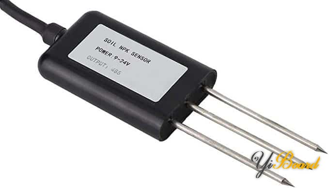
This sensor requires no chemical reagents. Due to its high measurement accuracy, fast response speed, and good interchangeability, it can be used with any microcontroller. However, you cannot use the sensor directly with a microcontroller because it uses a Modbus communication port. Therefore, you need to use a Modbus conversion module, such as RS485/MAX485, to connect the sensor to the microcontroller.
The sensor operates at 9-24V, resulting in very low power consumption. Its accuracy is up to within 2%. Measurement resolution for nitrogen, phosphorus, and potassium is as high as 1 mg/kg (mg/L).

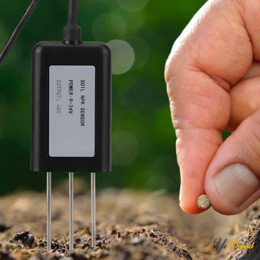
Using soil nitrogen, phosphorus, and potassium sensors, you can build your own Arduino soil NPK meter or any cloud-based IoT-based soil nutrient content monitoring system.
MAX485 TTL to RS-485 interface module
The MAX485 TTL to RS-485 interface module enables robust long-distance serial communication up to 1200 meters using RS-485 differential signals, suitable for industrial environments. It supports data rates up to 2.5 Mbit/Sec, but the maximum supported data rate decreases with increasing distance.

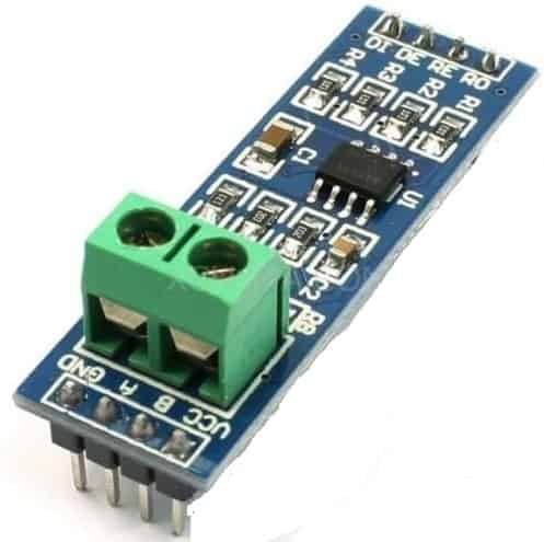
The controller outputs data at TTL level, and the RS-485 module is responsible for converting electrical signals between TTL and the differential signals used by RS-485. A significant advantage of RS-485 is that it can support multiple devices on the same cable.
Hardware connection between soil nitrogen, phosphorus and potassium sensor and Arduino
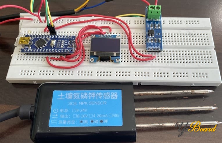
Now, let’s use the MAX485 Modbus module to connect the soil nitrogen, phosphorus, and potassium sensor to the Arduino Nano development board. The hardware connection diagram is as follows:

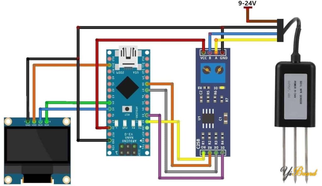
Use the software serial port to connect the R0 and DI pins of the Modbus module to the D2 and D30 pins of the Arduino development board. Additionally, we must pull the DE and RE pins high. To do this, connect the DE and RE pins to the D7 and D8 pins of the Arduino. The NPK sensor has four wires. The brown wire is VCC, which requires a 9V-24V power supply. The GND pin is black; connect this pin to the Arduino’s GND. The blue wire is pin B; connect it to pin B of the MAX485. The yellow wire, pin A, connects to pin A of the MAX485 module.
The 0.96-inch OLED display uses an I2C interface. Connect the VCC and GND pins of the OLED display to the Arduino’s 3.3V and GND pins, respectively. Additionally, connect its SDA and SCL pins to the Arduino’s A4 and A5 pins. You can assemble the circuit on a breadboard according to the circuit diagram.

Modbus commands related to nitrogen, phosphorus, and potassium sensors
Modbus commands can instruct Modbus devices:
1. Change the value of one of the registers, writing to the coil and holding registers.
2. Read I/O ports: Read data from the Discrete and Coil ports.
3. The command device sends back one or more values contained in its coil and holding register.
A Modbus command contains the Modbus address (1 to 247) of the device it is intended to use. A Modbus address is also called a query frame. Only the addressed device will respond to the command and take action, even if other devices may receive it.
The nitrogen, phosphorus, and potassium (NPK) sensor has three different query frame frames for reading the levels of nitrogen (N), phosphorus (P), and potassium (K). The command formats for the query frames are provided with the instruction manual. For NPK data, the following separate query frames are used:
1. Nitrogen : {0x01,0x03, 0x00, 0x1e, 0x00, 0x01, 0xe4, 0x0c}
The query frame for retrieving soil nitrogen values is:


You will receive the following response:

Soil nitrogen can be calculated based on the received response. For example, if you receive a response value of 0020, the soil nitrogen value will be:
0020 H (hexadecimal) = 32 (decimal) => Nitrogen = 32 mg/kg
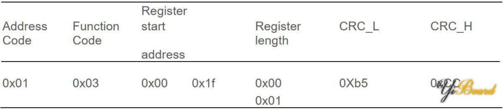
2. Phosphorous : {0x01,0x03, 0x00, 0x1f, 0x00, 0x01, 0xb5, 0xcc}
The query frame for retrieving soil phosphorus values is:

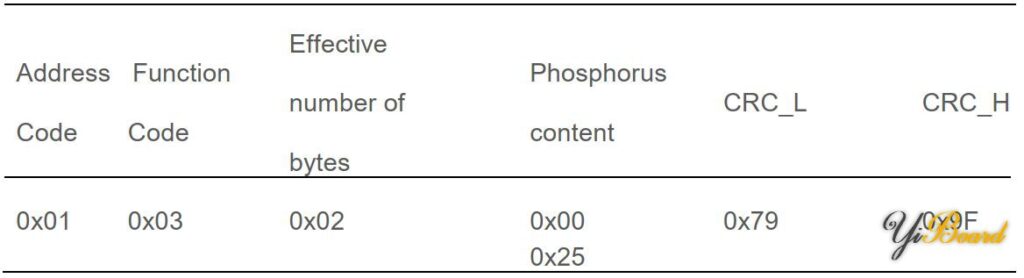
You will receive the following response:
You can calculate soil phosphorus based on the received response. For example, if you receive a response value of 0025, the soil nitrogen value would be:
0025 H (hexadecimal) = 37 (decimal) => Phosphorus = 37/kg
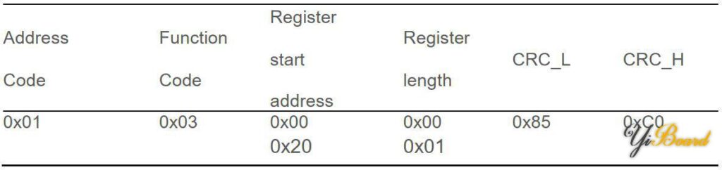
3. Potassium : {0x01,0x03, 0x00, 0x20, 0x00, 0x01, 0x85, 0xc0}
The query frame for retrieving soil potassium values is:

You will receive the following response:

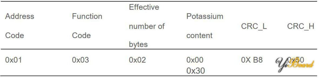
You can calculate soil potassium based on the received response. For example, if you receive a response value of 0030, then the soil potassium value would be:
0030 H (hexadecimal) = 48 (decimal) => Potassium = 48 mg/kg
code
Below is code for connecting a soil nitrogen, phosphorus, and potassium sensor to an Arduino and obtaining soil nutrient values from the sensor via Modbus commands. You can send commands and then check the values in the HEX code. The hexadecimal code needs to be converted to decimal to obtain the measured soil nutrient content data.
Since we’re using an OLED display to show soil nutrient values (nitrogen, phosphorus, and potassium) in mg/kg, you’ll need an OLED library. Download the following OLED library and add it to your Arduino IDE.
Observing soil NPK data on an OLED display
After uploading the code to the Arduino Nano development board, initialize the OLED and sensor. The sensor needs some time to stabilize, and the initial readings may be incorrect.
Once the sensor stabilizes, you can insert it into the soil to obtain NPK readings. The nitrogen, phosphorus, and potassium content in the soil will be displayed in mg/kg.

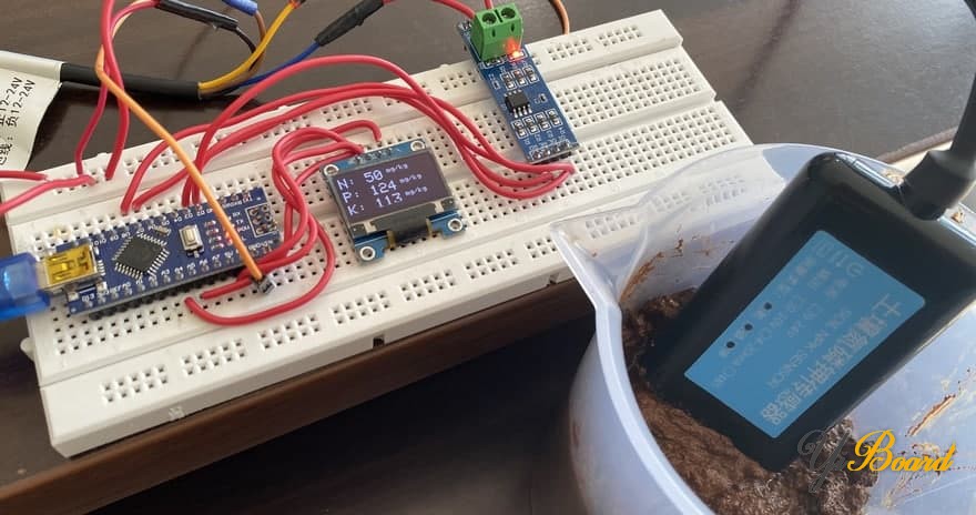
Similarly, place the sensor in different soil samples. You will see that the NPK content varies depending on the soil type.

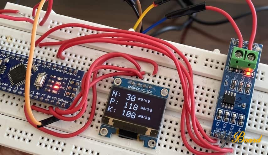
The above explains how to connect a soil nitrogen, phosphorus, and potassium sensor to an Arduino and obtain NPK readings. If you have any questions, please feel free to reply below this post.
Download the source code
This content is available to logged-in users only.
هذا المحتوى متاح فقط للمستخدمين المسجلين.
Ce contenu est réservé aux membres connectés.
🔑 Login 📝 RegisterLog in or create a free account to access downloads and exclusive content.