


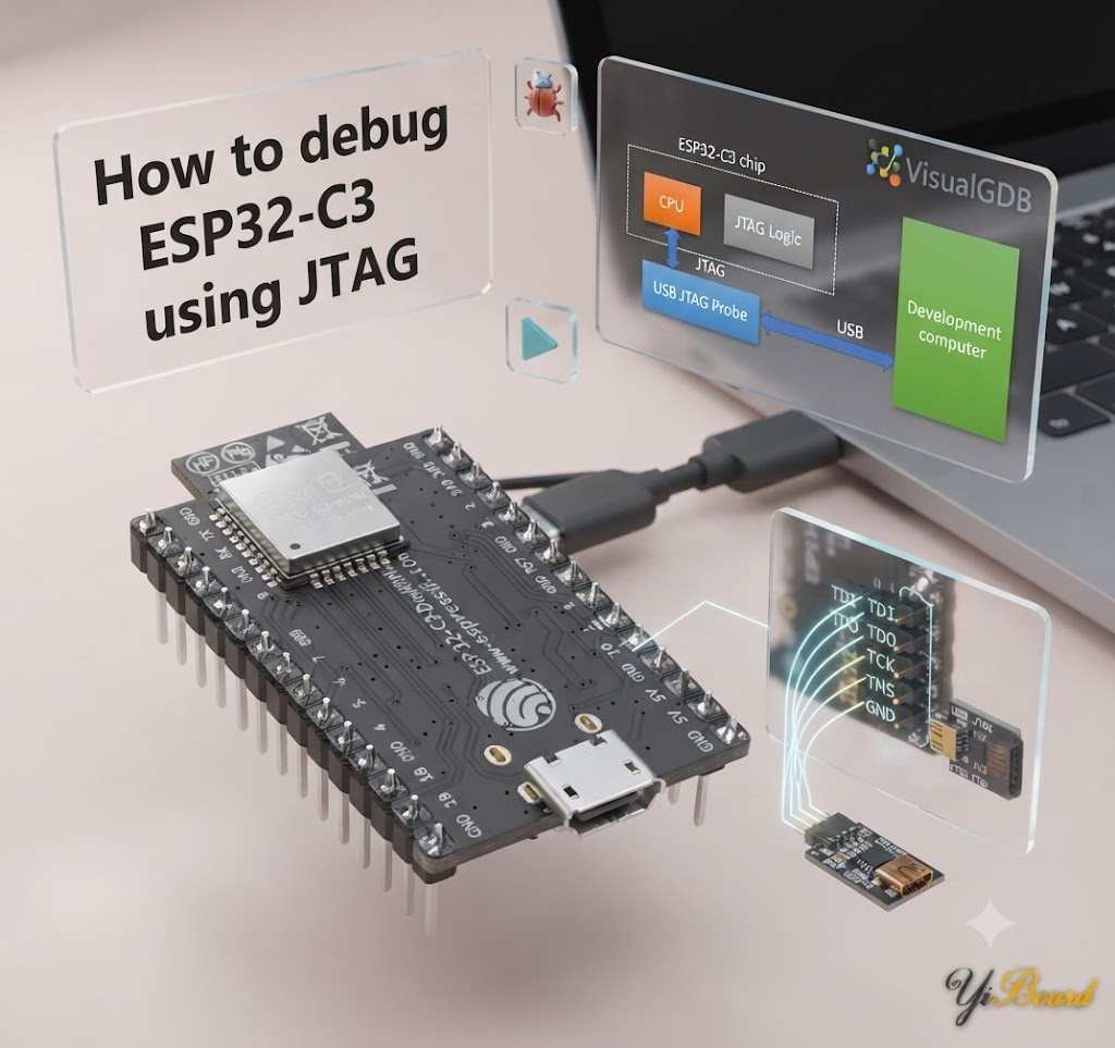
How to debug ESP32-C3 using JTAG
This article introduces how to create a basic project for the RISC-V-based ESP32-C3 device and how to debug it using JTAG. We will demonstrate all the necessary wiring on the ESP32-C3-DevKitM development board, as well as the steps required to configure the software.
The ESP32-C3 chip includes its own on-chip USB-to-JTAG engine, so debugging can be performed by connecting an auxiliary USB cable to a special debug USB pin (Option A). Alternatively, debugging can be performed using an external JTAG probe (Option B), but this requires the additional setup described here .

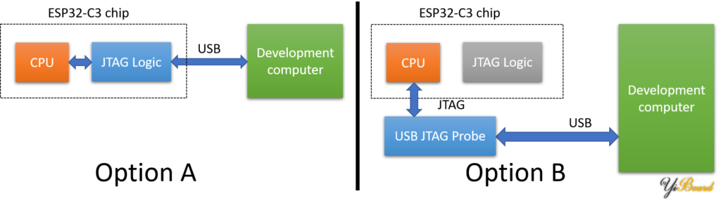
To debug the ESP32-C3 using the built-in JTAG engine, you need to use an auxiliary USB cable and connect it to the following pins on the development board:
| USB signal | Typical wire colors | ESP32-C3 signal name | ESP32-C3-DevKitM Pin Names |
| D- | White | GPIO18 | J3.13 |
| D+ | green | GPIO19 | J3.14 |
| V_BUS | red | 5V | J1.13 or J1.14 |
| GND | black | GND | J1.15 |

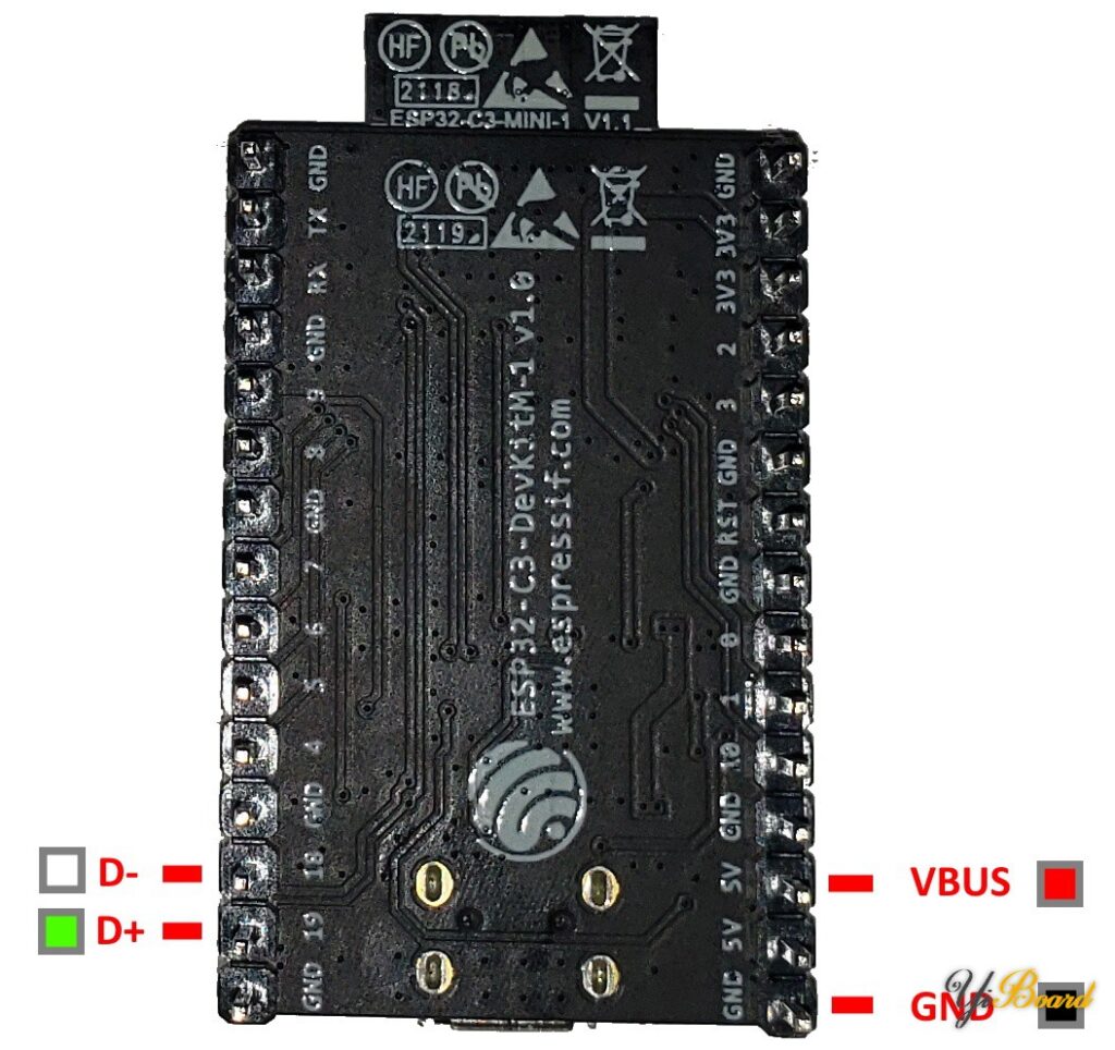
The settings after connection is complete are as follows:

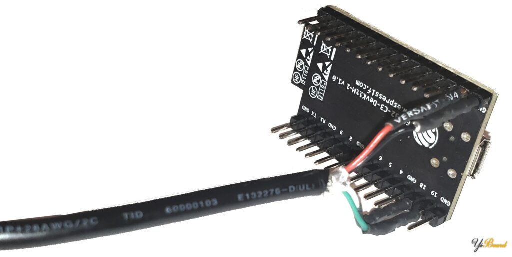
Please note that since the auxiliary USB connection also powers the board, you do not need to connect another cable to the main USB connector.
If you wish to use an external USB-to-JTAG probe, you will need to connect the following signals according to the Espressif documentation:
| JTAG signal | JTAG20 pin | ESP32-C3 signal | ESP32-C3-DevKitM pin |
| TMS | 7 | IO4 | J3.11 |
| TDI | 5 | IO5 | J3.10 |
| TCK | 9 | IO6 | J3.9 |
| TDO | 13 | IO7 | J3.8 |
| GND | 4 | GND | J3.1 |
After completing all wiring settings, please follow these steps to create a basic project and debug it:
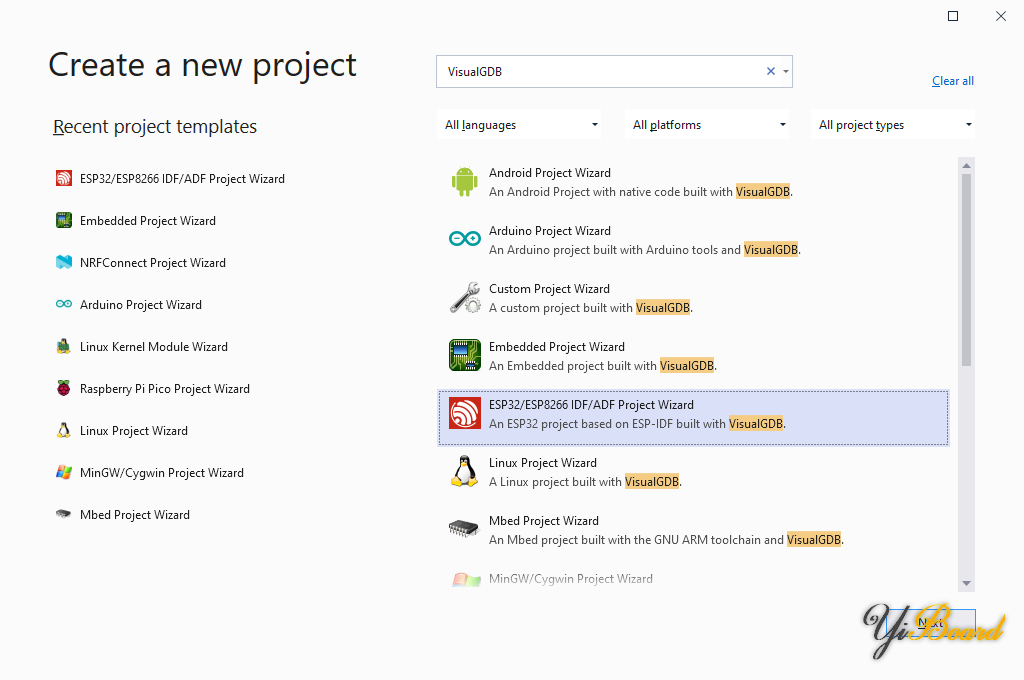
1. Launch Visual Studio, and then open the VisualGDB ESP32 Project Wizard:

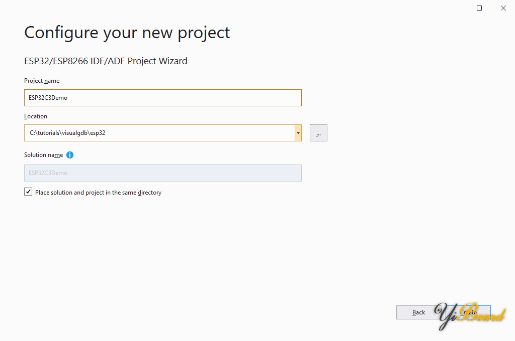
2. Choose a name and location for your project:
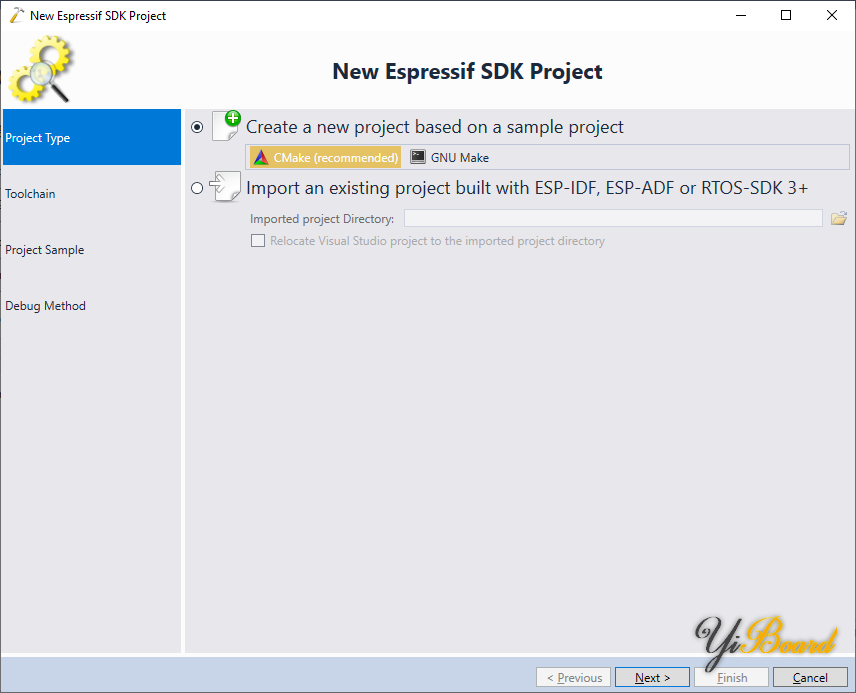
3. Use the default CMake build system:

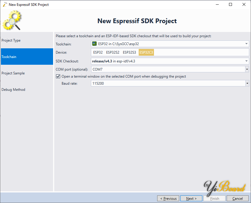
4. Ensure you are using VisualGDB 5.6+, the esp32-gcc 8.4.0-r3 toolchain or later, and ESP-IDF 4.3 or later. Then, select the ESP32C3 chip in the wizard:
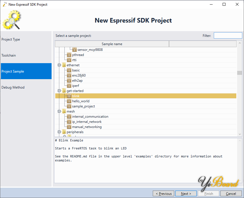
5. Continue cloning the basic “blink” example:
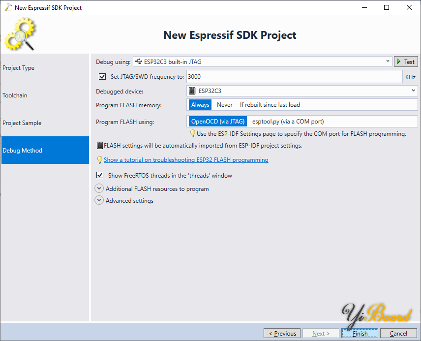
6. Connect the auxiliary USB cable as shown at the beginning of this article. VisualGDB will automatically detect the ESP32-C3’s built-in JTAG interface; select it on the Debug method page. Click “Test” to verify the connection:
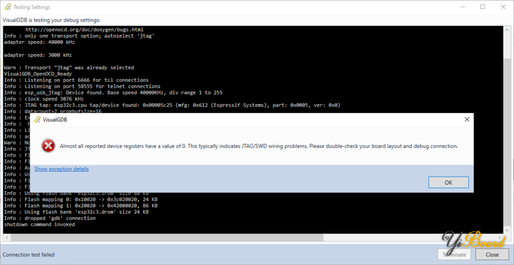
7. Use the “Test” button to verify the connection. Note that VisualGDB may report most device registers as set to 0. This is the expected result for an ESP32-C3 device and does not indicate an error.

8. Finally, click ” Finish ” to create the project. Now you will be able to build and debug it as usual:

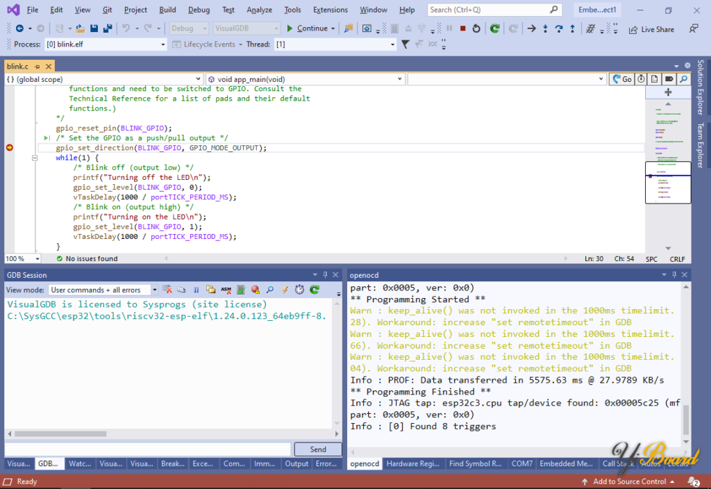
9. Note that the default blinking example does not blink the onboard LED. Instead, it configures IO5 (typically used as the TDI signal for external JTAG debugging) as an output and toggles it slowly. To debug code using an external JTAG debugger, in addition to following the steps described here, you will need to disable this feature (e.g., by changing BLINK_GPIO).