


Introduction
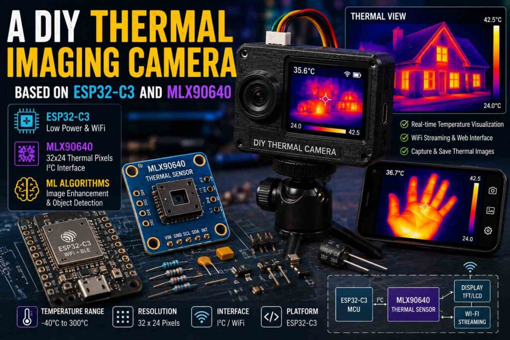
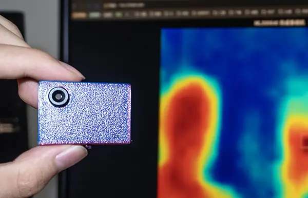
OpenThermal, also known as IRCam, is an open-source project for a compact thermal imaging camera built around the MLX90640 infrared sensor and the ESP32-C3 microcontroller. The device creates its own Wi-Fi access point, after which the thermal image can be viewed directly in a smartphone or computer browser. No additional screen, separate app, or complex network setup is required for basic use. The project is published as open source and permits modification and commercial use under the MIT license.
The author positions the device as an inexpensive, portable, and convenient alternative to professional thermal cameras, primarily for finding overheating components when debugging electronic boards. This is a logical use case: repairing and diagnosing electronics often doesn’t require the high detail of an industrial thermal camera, but it’s very useful to quickly see which chip, regulator, MOSFET, resistor, or trace is heating up more than the others.

What the Device Can Do
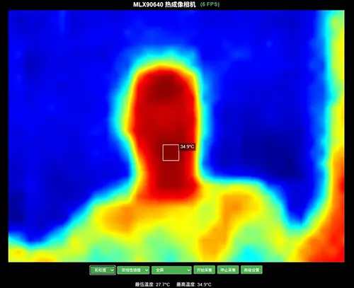
The core idea of the OpenThermal project is to offload processing and display of the thermal image to the browser. The device itself reads data from the MLX90640 infrared array, transmits it via the ESP32-C3, and a web interface displays the thermal map on the user’s screen.
Key features:
- viewing the thermal image through a browser
- ESP32-C3 operating in Wi-Fi access point mode
- built-in HTTP server
- connection from a phone, tablet, or computer
- support for multiple color palettes
- image interpolation from the original 32×24 pixels to larger resolutions
- automatic detection of the hottest point
- adjustable temperature range
- adjustable emissivity — the surface’s emission coefficient
- FPS display
- support for up to 4 simultaneous clients
Important: the sensor’s physical resolution remains 32×24 pixels. All the larger display modes — for example 96×72, 160×120, 224×168, 288×216, or 384×288 — are software interpolation. This makes the image visually nicer and easier to read, but doesn’t turn the sensor into a genuine high-resolution thermal imager.

Main Project Components
MLX90640 — Thermal Imaging Sensor
At the heart of the camera is the MLX90640, an infrared thermal sensor with 32×24 pixels — 768 FIR pixels in total. The sensor has a digital I²C interface, as well as built-in means for measuring the chip’s own temperature and supply voltage (Melexis). According to Melexis, the MLX90640 is designed to measure object temperatures in the range of −40°C to 300°C, with typical object-temperature accuracy stated at around ±1°C under proper operating conditions.
The OpenThermal project uses the MLX90640 BAA variant, priced at roughly 2,500 rubles (link). The MLX90640 comes in different versions that vary by field of view, so anyone replicating the project needs to carefully choose the right sensor variant.

ESP32-C3 — Microcontroller and Wi-Fi
The ESP32-C3 was chosen as the main controller. It’s an inexpensive Espressif microcontroller with Wi-Fi and Bluetooth 5 LE, built on a single-core 32-bit RISC-V core. Espressif specifies clock speeds up to 160 MHz, 400 KB of SRAM, and support for various interfaces including I²C, SPI, UART, and other peripheral blocks (Espressif Systems).
The ESP32-C3 is convenient for this project for several reasons:
- it’s fairly cheap
- it has built-in Wi-Fi
- it can operate as an access point
- it’s suitable for a compact device
- it can serve the web interface and exchange data with the MLX90640 over I²C
The firmware was developed in the PlatformIO environment using ESP-IDF.
How OpenThermal Works
The device’s operation can be broken down into several parts.
First, the MLX90640 reads thermal data. Each frame is an array of temperatures corresponding to 768 points. Then the ESP32-C3 receives this data over I²C, processes it, and makes it available through the built-in web server. The user connects to the device’s Wi-Fi network and opens a web page, where JavaScript code displays the thermal map on an HTML Canvas.
The architecture looks like this:
MLX90640 → I²C → ESP32-C3 → Wi-Fi AP → browser → Canvas / thermal mapThe project includes:
- a separate FreeRTOS task for capturing frames
- HTTP handlers for the web interface and API
- JavaScript for displaying the image
- color-conversion algorithms
- interpolation
- temperature-range smoothing
- hottest-point detection
In effect, the ESP32-C3 doesn’t function as a “camera” in the usual sense but rather as a mini thermal-data server. The actual image is formed on the browser side.

Connecting the MLX90640 to the ESP32-C3
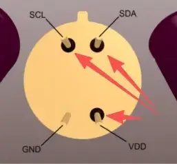
The project uses the following I²C lines:
| ESP32-C3 | MLX90640 | Purpose |
|---|---|---|
| GPIO5 | SCL | I²C clock line |
| GPIO4 | SDA | I²C data line |
| 3.3V | VDD | power |
| GND | VSS | ground |
The I²C frequency specified in the code is 400 kHz, and the MLX90640 address is 0x33. A 768-value array is used to store each frame’s temperature data.
When building the device yourself, it’s important to pay attention to the length of the I²C wiring, soldering quality, and sensor power supply. The MLX90640 is sensitive to connection errors, and a poor SDA/SCL contact can result in no image, unstable operation, or read errors.

Software Structure
The project structure includes several key parts:
src/
  main.c                 — main firmware logic

lib/
  MLX90640/              — driver and sensor algorithms
    MLX90640_API.h
    MLX90640_API.cpp
    MLX90640_I2C_Driver.h

data/
  web_script.js          — web interface JavaScript

platformio.ini           — PlatformIO configuration
partitions.csv           — ESP32 partition table
extra_script.py          — script for flashing JS files
Main Firmware
main.c contains:
- I²C setup
- MLX90640 initialization
- I²C read/write functions
- frame-capture task
- Wi-Fi access point startup
- HTTP server
- handling requests from the web interface
- HTML page generation
Web Interface
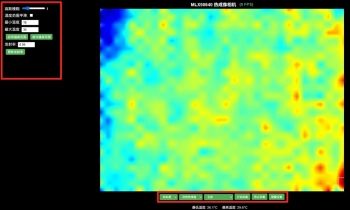
The web_script.js file handles displaying the thermal image. It receives data from the ESP32-C3, draws it on a Canvas, applies color maps, and scales the image. The project includes several color schemes, including options like heat map, rainbow, turbo, and others.
Users can adjust image parameters directly from the browser: interpolation resolution, color palette, temperature range, emissivity coefficient, and other settings.

Building and Flashing
PlatformIO is used for flashing. The basic process looks like this:
pio run
pio run --target upload
After flashing, the device starts up automatically. The ESP32-C3 creates a Wi-Fi network named IRCAM-XXXX, where XXXX is a random 4-character combination. After connecting to this network, open ircam.com or 192.168.4.1 in your browser. The password is 12345678.
Soldering and Assembly Notes
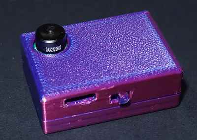
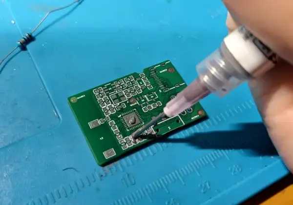
This isn’t a project you can just wire together on a breadboard. The device is compact and includes a charging section, power, controller, sensor, and enclosure, so careful assembly is critical. A particularly important point is soldering the thermal imaging module — it’s not recommended to solder the thermal head flush against the board, as this can cause short circuits. It’s better to leave a small gap. Another common issue involves the USB Type-C connector: if the computer doesn’t detect the device or there’s no reaction when plugging in USB, the first thing to check is the soldering of the D+ and D− lines.
What This Camera Can Diagnose
OpenThermal is especially useful for tasks where you need to quickly see heat distribution:
- finding overheating components on a PCB
- checking DC-DC converters
- diagnosing MOSFETs, drivers, regulators
- locating short circuits via local heating
- checking connector and trace heating
- assessing the thermal behavior of enclosures and heatsinks
- educational heat-transfer experiments
- monitoring simple household or engineering objects
For electronics repair, this kind of camera can be very convenient. For example, if a board has a power short circuit, a specific component often starts heating up when current is limited on a lab power supply. A thermal camera lets you find it faster than using your finger, alcohol, a freeze spray, or lengthy continuity testing.

Project Limitations
Despite its practical usefulness, OpenThermal shouldn’t be seen as a full replacement for a professional thermal camera.
Main limitations:
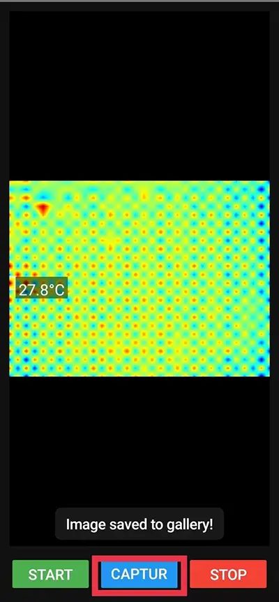
- physical resolution of only 32×24 pixels
- interpolation improves the look of the image but doesn’t add real detail
- accuracy depends on surface, angle, distance, emissivity, and environmental conditions
- shiny metal surfaces can produce inaccurate readings
- the sensor and board can heat up themselves, affecting measurements
- quality assembly requires careful soldering
- serious measurements require calibration
Temperature measurement accuracy depends on environmental factors, and regular calibration is recommended for precise measurements.
Conclusion
OpenThermal / IRCam is an interesting open-source project for a compact Wi-Fi thermal imaging camera. Its strength lies in its simple architecture: the MLX90640 reads thermal data, the ESP32-C3 sets up Wi-Fi and a web server, and the browser displays the thermal map. This makes the camera self-contained, portable, and convenient for quick electronics diagnostics. It’s not a professional thermal imager or a lab-grade measuring instrument, but as a tool for finding overheating, learning, and experimentation, the project looks very solid. It’s especially valuable that the source code is open — it can be modified, the interface refined, and the device adapted to your own needs.
Original Post
Source files
This content is available to logged-in users only.
هذا المحتوى متاح فقط للمستخدمين المسجلين.
Ce contenu est réservé aux membres connectés.
🔑 Login 📝 RegisterLog in or create a free account to access downloads and exclusive content.