Concentric coil for IDX Pro/TGSL
This document is intended to demonstrate one method of constructing Concentric Co-planer coils. While it is targeted toward the home hobby builder it is not as simple as the more popular DD coil configuration.
The Concentric coil configuration does however offer some advantages over the DD coil. Some of these advantages include cost of construction, lighter weight, easier pinpointing, greater detection distance for a given diameter, better discrimination and iron rejection.Even though constructing the Concentric coil can be a little tricky, it will be demonstrated that it can be done successfully! In this example we will be building a coil to match a White ‟s coil for the IDX project.While the specifications for a White ‟s coil are presented here, similar construction methods can be used for a multitude of coils.
To begin with, let us take look at our desired specifications for our coil:
TX circuit
- Resonance frequency 6590 Hz
- Capacitance 1uF
- Inductance 580 uH
- Resistance 2.3
RX circuit
- Resonance freq. 4680 Hz
- Capacitance 33nF
- Inductance 35 mH
- Resistance 122 Ohms
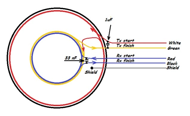
Let ‟s look at the basic layout of how to wind each coil:
Foam board – 1 2 ” (11mm) thick, 12 ” X 12 ”. I used “large cell ”foam that is relatively stiff and brittle from a craft store.
• Cardboard – anything thin and stiff.
• .202mm (32 AWG) wire – about 450 ft.
• .644mm (22 AWG) wire – about 70 ft.
• 33nF capacitor (polystyrene)
• 1uF capacitor (polystyrene)
• 4 „ of Belden 8723 cable.
• Cable strain relief.
• Cyan glue.
• White glue.
• Black silicone sealer.
• Epoxy.
• 8 ” coil shells.
For illustration purposes – start with a sheet of 1/2 inch foam boardfrom a craft store – It’s “large cell” foam, that is somewhat brittlebut also stiff.
It is then cut into a donut shape to accept a spool for the Rx coil.The Rx coil is wound on a homemade spool of cardboard with a foamcenter. The foam “donut” is then glued to a sheet of stiff cardboardand the Rx spool is glued into the center.
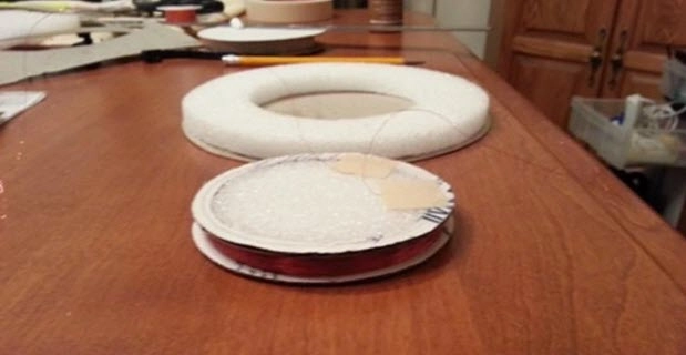
The Tx coil is made on a separate former and held together with Cyan glue. Then this coil is simply glued into a channel cut into the foam.

Alternately, it can be wound in a ¼” x ¼” channel around the outside of the “donut” foam core. I have done it both ways, and they both work.
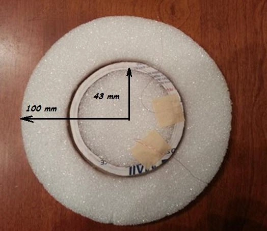
Rx coil – 3.25″ diameter – “about” 440t for 32 AWG wire (35 mH) wound counter clockwise + 33nF cap.
Tx coil – 7.5″ diameter – 35t for 22 AWG wire (583uH) wound counter clockwise + 1 uF cap.
Bucking coil – about 11 turns wound on top of Rx coil wound clockwise.
NOTE: The above specifications are not to be solely relied on! Your specific build needs to be measured and verified or the phasing will most likely incorrect! The IDX project is not so tolerant to the coil
values being off.

The bucking coil is wound opposite the direction of the Tx coil – directly on top of the Rx coil. For the best null, the hot end of the Tx coil must be connected to “Tx start” (P8 pin 1). The grounded end of
the Rx coil must be the wire closest to the bucking coil – ” Rx end” (P8 pins 3 & 4).
For the tricky part – When the bucking coil is wound around the Rx coil opposite direction from the Tx coil, the frequency goes up by about 60Hz, so a turn or 2 will have to be added to the Tx coil to bring the frequency back down to 6.59kHz. After tuning and nulling, the inner ring is filled with slow cure epoxy.
Finally, a second sheet of cardbard is glued to the exposed side of the foam “donut” . This makes the whole assembly very rigid .


In order for the coil to be stable and not react to the effects of ground capacitance, it must be shielded. There are two easy ways to accomplish this – either by building a shield on the inside of the shells or by building a shield directly on the cardboard. Either method will work. The cardboard can be sprayed with conductive graphite or the shells can be sprayed. For this project, I chose to spray the inside of the shells. A cheap source of graphite spray is a hardware store.
This is a dry spray lube that can be picked up at a “Home Depot” hardware store for under $5.00.

When applied, it leaves a conductive coating that has a resistance of about 35k Ohms from one end of the shell to the other. In this project, I masked off a small strip of tape that when removed, leaves a small gap in the conductive coating. I‟m not really sure if this is required as I have built shells with and without a break using graphite and both methods work. In this case, I am using a break just because it is a best practice. Depending on how conductive the coating is, a
break may be required to stop any eddy currents in the shield. I‟m going to suggest doing it anyway.
An effective method of attaching a drain wire to the graphite shield is to mix a spot of DAP rubber contact cement with powdered graphite into a slurry. Then, glue the wire to the shield. It‟s conductive! This drain wire will then be soldered to the cable shield.

The top shell is shielded in the same manner with a drain wire of its own. The picture below shows the top shell before being sprayed. I will use an industrial strength double stick tape to secure my coil “sandwich” to the top of the shell . I just peel off the top layer of paper after graphite is applied to expose the sticky surface.

Finally, a strain relief is installed and the Belden cable is routed. The drain wire from the top is joined with the drain wire from the bottom. Then the two halves of the shells are jointed together and secured using black “RTV” silicon. As shown below.

For other size coils, the above idea can easily be scaled up. To do so, I recommend that you download the coil inductance calculator here. You will need to recalculate the number of turns required for the Tx and Rx coils.