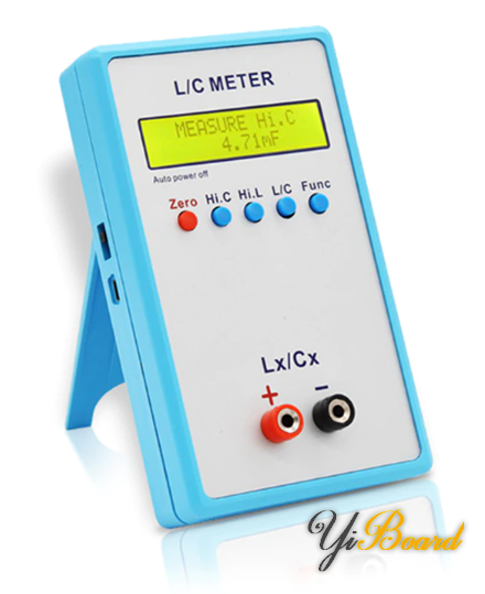
Inductance and Capacitance Measurement Using PIC18 Microcontroller

When designing or debugging electronic devices, it is very important to know the values of the components used on the circuit board. Most components can be easily measured and identified using a multimeter, but most common multimeters do not have the function of measuring inductance and capacitance because this is rarely needed. However, without capacitance, there is actually no circuit, and complex circuits may contain inductors. LCR (inductance-capacitance-resistance) meters can be used to determine the above components, but generally such meters are very expensive.
In this article we will share a method that can measure inductance and capacitance with some accuracy. For this, we can use a common 8-bit microcontroller. I have used PIC18F452. Of course, any other microcontroller will be equally suitable for this purpose as long as the calculations and procedures are kept. We also need a small external analog circuit based on the LM393 dual analog comparator. This circuit is a simple Hartley oscillator . The idea is to measure the frequency or time period of the oscillator. When a new component such as an inductor is introduced to the oscillator, both its frequency and time period will change. We can then back-calculate the component values.
The PIC18F452 is an 8-bit PIC18F series microcontroller. It is much more powerful in terms of hardware than the popular PIC16F877A or PIC16F887. However, we do not need any other hardware except the capture compare module (CCP) and the timer. The main reason for using the PIC18F is that it has an operating clock speed of 40MHz.
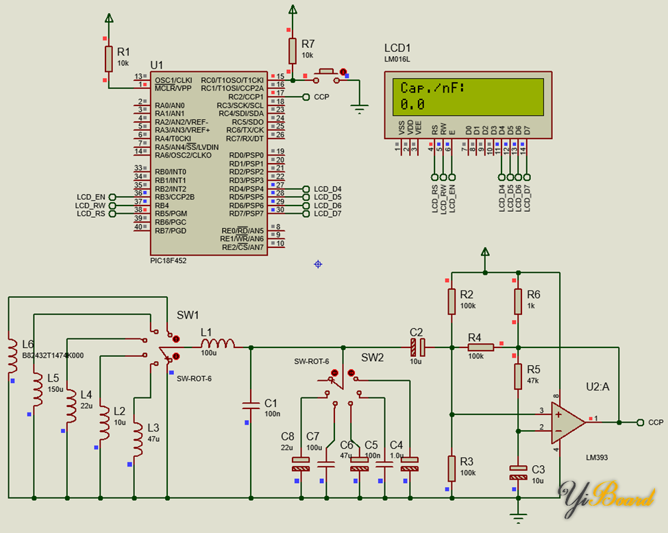
Circuit Schematic
The following is the schematic diagram of the inductance and capacitance meter:
Required Components
We will need all the components shown in the circuit diagram. Components L2 to L6 and C4 to C8 are test components. Rotary switches SW1 and SW2 are only used in the simulation schematic and do not exist in reality. A 2×16 alphanumeric LCD is used to display information. A push button connected to pin C0 is used for mode selection.
Code
Code Description
Based on the theory discussed, we need the high processing speed of PIC18 along with the timer and capture modules. We also need an LCD to display the results. The setup() function shown below shows these modules and their settings.
The CCP1 module is set to rising edge capture. This means that CCP1 will capture the count of Timer 1 when a rising edge is detected. The CCP module in the PIC microcontroller usually works in the Timer 1 module, so its count is captured. Capturing two consecutive rising edges will result in a period measurement of the input waveform. This is what we need most.
To further make it obvious that things work in a concurrent fashion, interrupts are used. The CCP1 interrupt fires when a rising edge capture occurs, and the Timer 1 interrupt is used to keep track of timer overflows. When handling a Timer 1 overflow, the current and previous capture counts are stored. These will be used to determine the time period. Timer 1 will rarely overflow, as it will only overflow if the frequency of the input waveform is very low, which in practice will never happen.
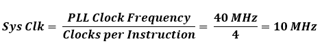
The PLL of the PIC18 is used to up-clock the external 10MHz crystal oscillator clock to 40MHz. This is reflected in the fuse bits and clock settings.
However, the PIC typically requires 4 clock cycles per instruction, so the effective system clock frequency is 10MHz.
Therefore, one tick of Timer 1 is:
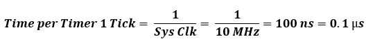
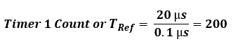
Therefore, at a base frequency of 50kHz (20 µs), Timer 1 will count:
The reference inductor and capacitor values can be simply known from the following equations:
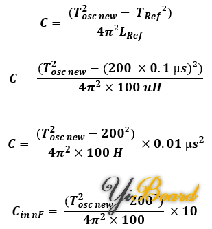
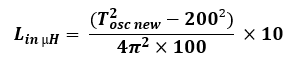
The same applies to inductance measurements, and the formula simplifies to:
Fixed constants are defined in defines at the top of the code
Now suppose we want to measure 220nF. Therefore, for this capacitance, the oscillator frequency will be:
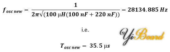
Timer 1 will count 355 counts while capturing this frequency from the oscillator.
Now, if we calculate back using the formula shown previously, we find that the value of the capacitor is:
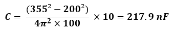
Yes, the reading is a little off from the actual value, but it is close enough. The error occurs because the timer can only count to whole numbers. This error can be cleverly compensated for in the code.
The button connected to pin C0 is used to select the inductance or capacitance measurement mode. Every time the mode is changed, a calibration is required. The calibration process is simple. We just need to leave our meter unconnected to anything except the reference capacitor and inductor, as shown in the circuit diagram below. This is the Hartley oscillator, the heart of the whole device.
During this time, the reference component value is measured and saved. This value will be subtracted during the unknown component measurement. During the calibration process, the meter’s display will show instructions not to place any external components.
After calibration is completed, the unknown components can be placed and measured accordingly. These tasks are completed in the main loop function of the program.
Demo
The following is a demonstration effect of measuring capacitance and inductance values:
All documents mentioned in this article can be obtained from the following links:


