
In my previous article about an SPI Flash and I2C EEPROM programmer built with an Arduino, the very first question/comment after publication was “Does it program PICs?” This question, of course, came from an inattentive reader, but it confirmed once again that although PIC microcontrollers are quite old, they still enjoy considerable interest among hobbyists, since a huge number of devices have been built around them over the years. However, flashing these microcontrollers is a real challenge. As is well known, there’s a variety of PIC programmers available: simple ones consisting of a few wires for an LPT or COM port (like JDM and similar designs), and USB programmers (PICkit 1, 2, 3, and their homemade clones). Both types have their pros and cons: the former are very easy to assemble but require ports that aren’t always available on modern PCs, let alone laptops. The latter are very convenient since they connect via USB and work with any modern (or not-so-modern) computer. However, they have a significant drawback: they aren’t cheap (even on a well-known Chinese marketplace, a PICkit2 costs around $15-20, while a PIC18F2550 microcontroller for building a homemade PICkit2 costs around $10 — and even then you might end up with a counterfeit, rebranded, or poorly made chip). Not every beginner, or even a more experienced hobbyist, will want to buy such a programmer if they only need it once or twice a year.
So after that comment, I got curious whether I could build my own PIC programmer — especially since I’d already tried “fighting” these microcontrollers before. Honestly, the first time I tried, I failed completely — I couldn’t even read the PIC16F73’s ID. But even then I realized this was an extremely difficult task, and not just because of my prior experience. I simply read several “Programming Datasheets” for various PIC families and was horrified: it turned out these chips have a ton of subfamilies, ranging from one or two members to several dozen, and there’s a huge number of such subfamilies. The most interesting part is that they’re all programmed differently: some have only 6-8 instructions, while others require you to push assembly code through the programmer! The only thing they have in common is the pin names for connecting a programmer (PGC, PGD, PGM, and MCLR) — that’s where the similarities end. Even the PIC16F84 and PIC16F84A, or the PIC16F628 and PIC16F628A, are completely different “beasts” in terms of programming! But that’s not all — the second, equally important problem is the HEX files for PICs. They have no standard either! A single file contains the CODE segment (the main program), the DATA segment (the EEPROM), and the configuration words. And the funniest part is that each subfamily places these segments at different offset addresses, and the number of configuration words also differs per family. Perhaps that’s when it finally dawned on me why the PICkit is so expensive — a programmer developer could go crazy trying to standardize the programming algorithms for such “delightful variety.” I can just imagine how Microchip’s engineers designed it back then: “Let’s make the next line programmable not with simple commands but with core assembly code, preferably reversed… So what? Programmers shouldn’t get too comfortable.”
Some time passed, I gained some experience with my own hardware and software designs, and I decided to give PICs another shot. I sketched a rough algorithm for how to more or less standardize the software, and I also worked through the programmer’s hardware. Let me start with that description.
I decided to use a 5-volt microcontroller as the basis for the programmer, since most PICs use 0-5V logic levels (except the PIC24 and dsPIC, which I didn’t even want to consider). I could have gone with something very cheap like the STC8, but decided those weren’t popular enough and opted for an AVR instead — especially since AVRs are used in the well-known Arduino boards that nearly every hobbyist has lying around, and they’re relatively inexpensive. However, an Arduino board or a bare AVR alone isn’t enough to program PICs. As many people know, PIC microcontrollers (most PIC16 and PIC18 parts) use high-voltage programming, meaning that to enter programming mode, a boosted voltage of 12-13V must be applied to a specific pin (MCLR). This requires an additional boosted voltage source and a circuit to control it. So in the first version of the circuit, I used a boost converter based on the MC34063A chip, so the programmer could be powered solely via USB. And it worked! But the joy of “victory” was short-lived. The programmer could read the firmware, read the ID, and read the configuration bits, but stubbornly refused to erase or write. In the programming datasheet, I found that write/erase operations require a VDD supply voltage of 4.5-5.5V. I decided to measure the VDD voltage during the read process and saw it drop drastically to 3.8V. Naturally, with such a drop, writing/erasing was out of the question. So I abandoned the boost-converter idea in favor of an additional external 12V power source. And that paid off — with an external 12V source, the erase and write processes worked! In the end, this second version of the circuit became the final design. The circuit turned out very simple. Instead of discrete logic buffer chips, I built the VPP and VDD voltage control switches (12V and 5V) using transistor switches (two stages each). The circuit also uses a 5V linear regulator (7805). I decided not to add 12V regulation, fearing that some PICs might require a higher voltage (12.5-13.5V) — with a 7812 regulator installed, it would be impossible to adjust the VPP voltage. The resulting circuit isn’t very complex — even a beginner with a fine-tipped soldering iron can handle it:
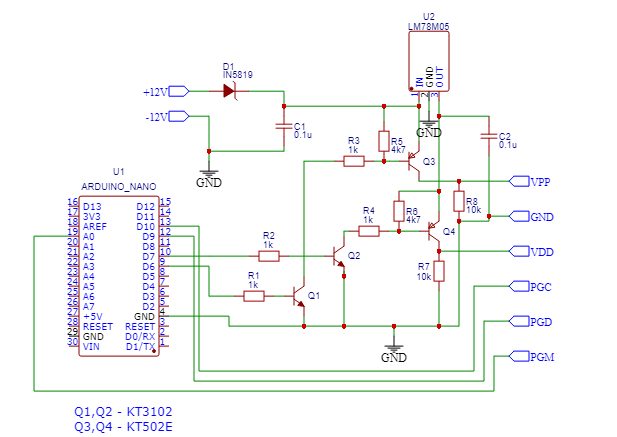
USB PIC programmer circuit (Arduino-based)
It looks something like this (all parts are SMD, mounted on the bottom side of the board):
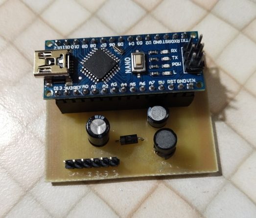
USB PIC programmer photo
The photo shows the first version of the board; I’m showing it purely to illustrate how to assemble a shield board for the Arduino Nano.
I built the final version of my programmer as a separate board using an ATmega328P. Its schematic is as follows:
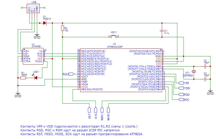
I didn’t draw the voltage control switches in this diagram, otherwise it would take up half the page — this diagram just shows the connection between the ATmega, the USB-UART converter, and the voltage control switches. My final programmer board looks like this (apologies for the flux residue and cotton fibers I used trying to clean it off):
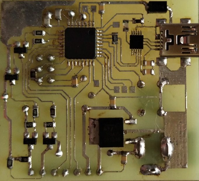
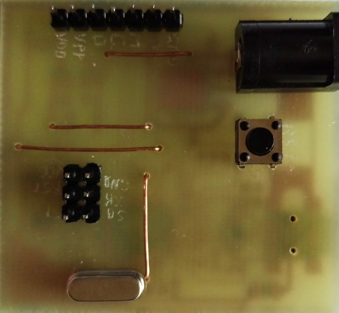
The board turned out quite compact — only 44×47 mm — thanks to the miniature CH340E USB-UART converter, which doesn’t require a crystal oscillator, and the ATmega in a TQFP32 package, which also doesn’t take up much space. The linear regulator and all small parts are SMD as well. For reference, I used MMBT3904 transistors (package marking “1AM”) for Q1/Q2, and BC856 transistors (package marking “3B”) for Q3/Q4. I’ll include a drawing of my PCB at the end of the article. That said, anyone can build a board using whatever components they have on hand. Incidentally, if your USB-UART converter has a DTR signal, it needs to be connected to the ATmega’s RESET pin via a 0.1µF capacitor, to enable automatic reset when programming the ATmega through the UART bootloader. The CH340E doesn’t have this signal, so the ATmega has to be reset manually using the reset button.
Now let’s talk about the software. As usual, I wrote the PC program in C# using MS Visual Studio. The first version of the program looked like this:
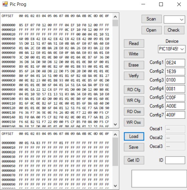
I don’t consider the program’s interface final, since I can’t predict what other parameters might exist for any given PIC family, or what might need to be added or removed. We’ll see as new microcontrollers get added.
As you can see, there are two large text fields for the CODE (top) and DATA (bottom) firmware segments, seven text fields for configuration words (I used the PIC18F4550 as the maximum case), a PIC model selection field, and a bunch of buttons with self-explanatory names. In the lower right corner there’s a text field for status information. I also added three “Oscal” fields as a placeholder; they’re not used yet, but I know that 8-pin PICs contain RC oscillator calibration bytes that can be accidentally overwritten, so these fields might come in handy later.
Using the program is very simple: connect the programmer to a USB port, and a COM port should appear. In the upper right corner of the program, select the COM port your programmer is connected to (if the programmer was plugged in after launching the program, click “Scan” to refresh the list of available ports), then click “Open.” If everything works, the indicator should turn green and a corresponding message will appear in the console at the bottom right. To verify the programmer is responding, click “Check” — the console should display “Programmer connected.” Next, select the PIC model in the “Device” field. Only after that can you read, write, or erase. There are some quirks when working with configuration words: when you load a HEX file, they’re automatically inserted into the corresponding fields (Config1–Config7); clicking “Write” writes them automatically right after the CODE and DATA segments, or you can click “WR Cfg” to write them separately. However, the config values aren’t written directly from the HEX file — they’re written from these fields, meaning that if you edit the values in these fields after opening the HEX file, your edited values are what gets written.
Since the program is still quite rough, many exceptions aren’t handled, meaning incorrect input can cause it to crash — for example, selecting one PIC model but opening a HEX file meant for a different model, or entering invalid characters into the Config fields (Cyrillic characters or anything outside “0-9, A-F”).
As for programming speed, it’s fairly decent — of course, read/write speed depends on the specific PIC model. Taking the PIC18F4550 as the most capable of the currently supported chips, read speed is about 2 kilobytes per second, with write speed naturally somewhat slower. Even with a 32-kilobyte CODE segment, the total read/write time isn’t bad at all.
I tried to write the program so it would be universal across any PIC family and wouldn’t need code changes when adding support for new models. To add new devices, I use a settings file (“pic.xml”) located in the program’s folder. It contains standardized structures with the necessary microcontroller parameters, which the program uses primarily to parse the HEX file. This means adding new PIC models is mostly a matter of editing the settings file, plus — to a greater extent — updating the ATmega firmware. The settings file looks like this:
<name model="PIC16F628A">
    <id>0x1060</id>
    <type>2</type>
    <f_size>4096</f_size>
    <f_psize>1</f_psize>
    <ee_size>128</ee_size>
    <f_start>0</f_start>
    <ee_start>002100</ee_start>
    <ee_type>0</ee_type>
    <conf1>002007</conf1>
    <conf2>none</conf2>
    <conf3>none</conf3>
    <conf4>none</conf4>
    <conf5>none</conf5>
    <conf6>none</conf6>
    <conf7>none</conf7>
    <oscal1>none</oscal1>
    <oscal2>none</oscal2>
    <oscal3>none</oscal3>
    <delay>4</delay>
    <word>3FFF</word>
</name>
As you can see, there are quite a lot of parameters — though it's still not as many as in a similar settings file for the K150 programmer.
Currently, the program doesn’t have the ability to save read data to a HEX file or work with oscal calibration bytes. I already have a rough idea of how I’ll implement HEX file saving; oscal support isn’t planned anytime soon.
Regarding the ATmega firmware — despite the article’s title, you won’t find any Arduino sketches here. The code is written in C. I used the Eclipse IDE with the AVR plugin (which uses AVR-GCC, the same toolchain as Atmel Studio). So all the *.h and *.c project files can be transferred to Atmel Studio without any changes. The code can also be ported to other AVR models with more flash memory (e.g., ATmega64, ATmega128, etc.) with minimal modifications. The only chip-specific part is the USART (configured for 57600 baud, transmit and receive, plus a receive-interrupt) — though even the USART module is nearly identical across most ATmega chips; you just need to rename the registers (e.g., UDR to UDR0, UCSRA to UCSR0A, etc.). All other functionality is implemented “from scratch.” Configuration of the PGD, PGC, PGM, VPP, and VDD pins is handled through macros:
#define PGD_PIN     1       //D9
#define PGD_PORT    PORTB
#define PGD_DDR     DDRB
#define PGD_IDR     PINB
#define PGC_PIN     2       //D10
#define PGC_PORT    PORTB
#define PGC_DDR     DDRB
#define PGM_PIN     0       //A0
#define PGM_PORT    PORTC
#define PGM_DDR     DDRC
#define VDD_PIN     7       //D7
#define VDD_PORT    PORTD
#define VDD_DDR     DDRD
#define VPP_PIN     6       //D6
#define VPP_PORT    PORTD
#define VPP_DDR     DDRD

#define PGD_HIGH    PGD_PORT |= (1 << PGD_PIN);
#define PGC_HIGH    PGC_PORT |= (1 << PGC_PIN);
#define PGM_HIGH    PGM_PORT |= (1 << PGM_PIN);
#define VDD_HIGH    VDD_PORT |= (1 << VDD_PIN);
#define VPP_HIGH    VPP_PORT |= (1 << VPP_PIN);
#define PGD_LOW     PGD_PORT &= ~(1 << PGD_PIN);
#define PGC_LOW     PGC_PORT &= ~(1 << PGC_PIN);
#define PGM_LOW     PGM_PORT &= ~(1 << PGM_PIN);
#define VDD_LOW     VDD_PORT &= ~(1 << VDD_PIN);
#define VPP_LOW     VPP_PORT &= ~(1 << VPP_PIN);
So reassigning the microcontroller's pins to any other pins isn't particularly difficult — just change the pin number and port letter.
There are two ways to flash the HEX file onto the programmer itself: using any AVR programmer if it’s a blank ATmega, or using programs for uploading HEX files to Arduino boards, such as XLoader, Arduino Uploader, and similar tools (this isn’t an advertisement for any particular third-party site).
The firmware currently takes up just over 5 kilobytes out of the 30 available on the ATmega328P (the Arduino bootloader takes up 2 kilobytes). So there’s still plenty of room, and support for many more families could be added.
Now, the important part: what chips are currently supported? I’ll say right away — not much yet. Since only about a week has passed from the start of development to writing this article, and I worked on it in my spare time, I’ve currently added and verified support (tested on a real device with this MCU) for the PIC16F628A (there are two more chips in its subfamily: the 627A and 648A). The PIC16F73 has also been verified (by comparing read/written data against a reference JDM programmer) — it has three siblings in the same family (F74, F76, F77). Support for the PIC18F4550 has been added and verified, and the PIC18F2550 has been added as well (since it’s electrically identical for programming purposes). The only thing I couldn’t get working was reading the ID for this family — perhaps my sample chip is defective. The last two chip families I mentioned each have several dozen microcontrollers, which could easily be supported just by editing the configuration file, without changing the ATmega firmware. They should work, but I don’t have anything to test them with yet.
My immediate plans include adding support for classic PICs like the PIC16F84A and its siblings (since I have one for testing), as well as the PIC16F87X family. Further support will depend on interest in the project and, possibly, help with testing the programmer. I’m not able to test everything myself, since I can’t afford to buy various PICs just for testing purposes.
That’s all for now. Thank you for reading. Constructive criticism is welcome in the comments.
Bill of Materials
Circuit #1 (Arduino Nano-based)
| Designator | Type | Value | Qty | Notes | Store |
|---|---|---|---|---|---|
| U1 | Arduino board | Arduino Nano 3.0 | 1 | Search in Otron store | |
| Q1, Q2 | Bipolar transistor | KT3102 | 2 | Search in Otron store | |
| Q3, Q4 | Bipolar transistor | KT502E | 2 | Search in Otron store | |
| U2 | Linear regulator | LM78M05 | 1 | Search in Otron store | |
| D1 | Schottky diode | 1N5819 | 1 | Search in Otron store | |
| R1-R4 | Resistor | 1 kΩ | 4 | Search in Otron store | |
| R5, R6 | Resistor | 4.7 kΩ | 2 | Search in Otron store | |
| R7, R8 | Resistor | 10 kΩ | 2 | Search in Otron store | |
| C1, C2 | Capacitor | 0.1 µF | 2 | Search in Otron store |
Circuit #2 (ATmega328P-based)
| Designator | Type | Value | Qty | Notes | Store |
|---|---|---|---|---|---|
| U1 | Chip | CH340E | 1 | Search in Otron store | |
| U2 | 8-bit AVR MCU | ATmega328P | 1 | Search in Otron store | |
| D1 | Schottky diode | 1N5819 | 1 | Search in Otron store | |
| Led1 | LED | any | 1 | Search in Otron store | |
| C1 | Capacitor | 0.1 µF | 1 | Search in Otron store | |
| C2, C3 | Capacitor | 16 pF | 2 | Search in Otron store | |
| R1 | Resistor | 560 Ω | 1 | Search in Otron store | |
| R2 | Resistor | 10 kΩ | 1 | Search in Otron store | |
| XT1 | Crystal resonator | 16 MHz | 1 | Search in Otron store | |
| KEY1 | Tactile button | any | 1 | Search in Otron store |
Download files
This content is available to logged-in users only.
هذا المحتوى متاح فقط للمستخدمين المسجلين.
Ce contenu est réservé aux membres connectés.
🔑 Login 📝 RegisterLog in or create a free account to access downloads and exclusive content.


