Solder the board with pure rosin or alcohol-rosin solution. After soldering with a toothbrush, wash off the rosin residues with alcohol.
After installation MUST once again check the correctness of installation according to the diagram and PCB!
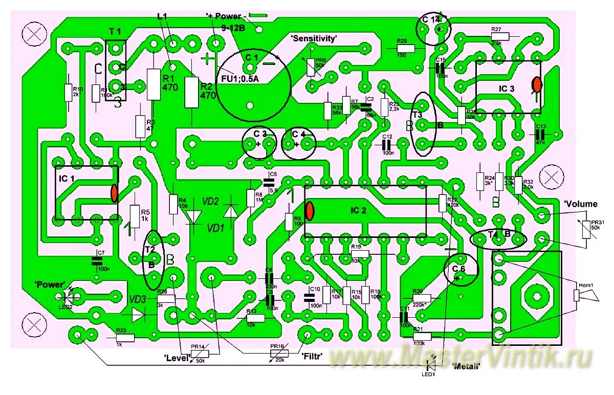
If everything is soldered correctly, then the device works immediately. But you will have to adjust the maximum sensitivity with trimming resistors PR6 “gain 1st stage”, PR15 “gain”, PR21 “delay”, PR25 “threshold of the generator”. PR26 – sets the threshold for the inclusion of the LED “low power”.

When you turn on for first time, be sure to check the current consumed by the device. At 12V should be 65 mA and at 9V – 48mA .
To power the device is better to use batteries. You can use the old battery from the laptop. 4 pcs of 3V = 12V.
When adjusting for maximum sensitivity with variable and trimming resistors in the headphones, RARE CRACKING is necessary .
Resistor R6 – amplification of the first stage (set on pin No. 1 TL074 9.5 V at 12V – voltage table below) together with the R15 “Gain” and R21 “delay” regulators achieve maximum sensitivity (there is a rare crackle in headphones! )
R25 – the threshold of the sound generator – set the moment of switching off the sound generator.
The multimeter can measure voltages (V) at the terminals of an op amp (without the presence of metal near the coil field) (power supply of the metal detector is + 12V) relative to the ground (-):
IC1 (NE555) | IC2 (TL074) | |
Pin.1= 0V | Pin.1 =9,5V | |
Pin.2 =6,4v | Pin.2 =5.5v | |
Pin.3 =10,4V | Pin.3 =9,5v | |
Pin.4 =12,0V | Pin.4 =12V | |
Pin.5 =8.1v | Pin.5 =3.3V | |
Pin.6 =6,4v | Pin.6 =3.5V | |
Pin.7 =6,4v | Pin.7 =0V | |
Pin.8 =12v | Pin8=2,2V | |
Pin9=9,2v | ||
Pin10=1,1v | ||
Pin.11 =0V | ||
Pin.12 =7,5v | ||
Pin.13 =7,7v | ||
Pin14 =1,8v | ||
IC3 (NE555) | IC4 (NE555) | |
vyv.1 =0V | Pin.1 =0V | |
vyv.2 =11,5V | Pin.2 =6.5v | |
vyv.3 =0V | Pin.3 =11V | |
vyv.4 =12V | Pin.4 =11,6V | |
vyv.5 =8.1v | Pin.5 =7,8V | |
vyv.6 =0V | Pin.6 =6.5v | |
vyv.7 =0V | Pin.7 =6,5v | |
vyv.8 =12v | Pin.8 =11,6V |
If you have an Oscilloscope, you can see on screen:
The frequency of the generator on IC1 Pin.3 (adjusted with R12,13 from 120 to 150 Hz); pulse on the collector of the transistor T2 (2N3904).
The operation of the delay circuit
The duration of the control pulse on the gate T1 (IC 3 adjusted with R21 from 50 to 100 μs).
Receiver operation
Transmitter pulse transmissions at receiver test points (outputs of output operational amplifiers (IC2) 1, 13, 14, and 4.
At the output of the sound generator IC (Pin. 3), a tone appears, with a frequency of 6000 Hz. The tone frequency is determined by the capacitor C16.
At the output of the chip through the volume control is the transistor T5 – BC640. The desired volume in the headphones is set by resistance PR35 .