Programmers

Programmer for PIC

As everyone knows, the micro-controller is controlled by a program recorded in its internal memory. Then for a beginner metal detector amateur trying to write a program to a mico-controller (especially a PIC) can turn into a big disappointment, and sometimes a small pyrotechnic show in the form of a fuming microchip. For these purposes, you can assemble a simple and inexpensive in the implementation of a homemade programmer, called a JDM programmer, according to the diagram below :

The necessary parts are listed bellow:
  • R1 – 10 kΩ
  • R2 – 10 kΩ (truncated). By adjusting the value of this resistor, you need to achieve about 13V at pin No. 4 (VPP) during programming.
  • R3 – 200 ohm
  • R4, R5 – 1.5 kΩ
  • VD1, VD2, VD3, VD4, VD6 – 1N4148
  • VD5 – 1N4733A (Voltage stabilization 5.1V)
  • VD7 – 1N4743A (Voltage stabilization 13V)
  • C1 – 100 nF (0.1 μF)
  • C2 – 470 microfarad x 16 V (electrolytic)
  • SUB-D9F – COM port connector
  • DIP8 socket – depends on the micro-controller you are using

The scheme uses an example of connecting such common micro-controllers as the PIC12F675 and PIC12F629 . To write a program to a controller of a different type, it is enough to throw the wires of the programmer in accordance with Figure, which is shown below.

Although the scheme itself is quite simple and will not cause difficulties in the assembly, but it also requires some attentions. Therefore, it would be nice to make a PCB for it. After some manipulations with the Sprint Layout program , PCB , drill and iron, the board has been manufactured .

Download the PCB source for the SprintLayout program at this link:  pp_programmator.zip 

If you wish, you can change it to fit your PIC controller type. For those who have decided to leave the board unchanged, I post the view from the side of the parts to facilitate installation.

At this point, the first step on the way to burn the firmware in the PIC  micro-controller came to the end. The second step will include connecting the programmer to a computer and working with the IC-Prog program . 
Unfortunately, not all modern computers and laptops are able to work with this programmer due to the banal absence of COM ports on them , and those installed on laptops do not provide the necessary 12V for programming . 
So turn on the computer and first install the program IC-Prog .
Connect the programmer to the COM port and start the newly installed application. For correct work it is necessary to perform a series of manipulations. Initially, you need to select the type of micro-controller that you are going to program. 


Next, go to the menu ” Settings” -> “Options “, in the window that appears, select the I2C tab and tick, as shown in the screenshot.

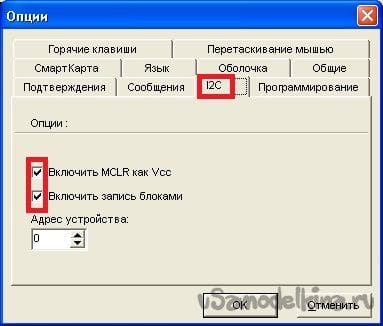
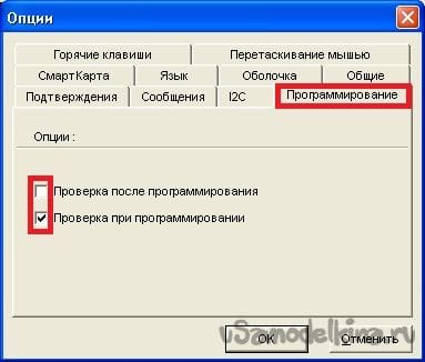
In the same window, go to the tab ” Programming ” and select the item ” Check while programming .” Check after the program may cause an error, 

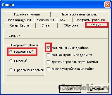
We continue to work with this window and go to the ” General ” tab . Here you need to set the priority of the program and be sure to use the NT / 2000 / XP driver. In some cases, the program may offer to install this driver and you will need to restart IC-Prog .

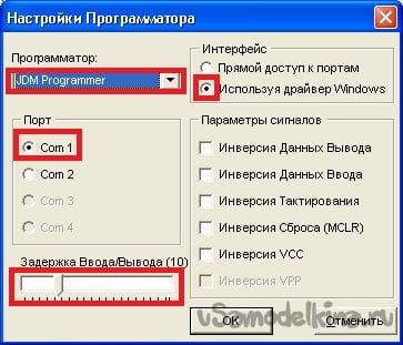
So, with this window the work is over. Now let’s move on to the settings of the programmer . Select in the menu ” Settings” -> “Programmer Settings ” or simply press the F3 key . The following window appears.

This is the setting of the program IC-Prog finished and you can go to the process of the firmware itself, but first we take the data from the micro-controller and see what’s written to it. To do this, click on the chip icon with a green arrow on the toolbar.

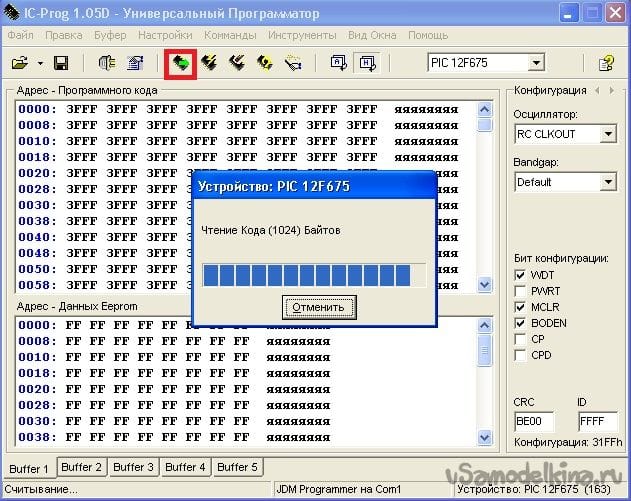
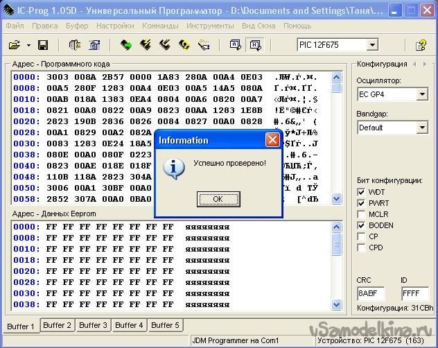
After some time, IC-Prog will give you a message about the successful verification of the newly recorded code in your PIC micro-controller.

Related Articles

Leave a Reply

Check Also
Close
Back to top button