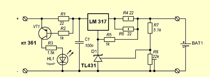
Scheme of a simple charger based on the LM317 chip with a charge state indicator:
The scheme is the simplest, the whole setup is reduced to setting the output voltage of 4.2 volts using the trimming resistor R8 (without the battery connected!) And setting the charge current by matching the resistors R4, R6. Power resistor R1 – not less than 1 watt. As soon as the LED goes out, the charging process can be considered complete (the charging current will never decrease to zero). It is not recommended to keep the battery in this charge for a long time after it is fully charged. The LM317 chip is widely used in various voltage and current stabilizers (depending on the switching circuit). Sold at every corner and costs a penny at all.
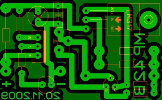
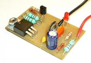
Analogs of the LM317 chip are: GL317, SG31, SG317, UC317T, ECG1900, LM31MDT, SP900, KR142EN12, KR1157EN1 (the last two are of domestic production). The charging current can be increased to 3A, if instead of LM317 take LM350. The printed circuit board and circuit assembly are shown below:
The disadvantage of the circuit: the supply voltage must be within 8-12V. This is due to the fact that for normal operation of the LM317 chip, the difference between the battery voltage and the supply voltage must be at least 4.25 Volts. Thus, it will not be possible to power the USB port.
LM317 Charger Schem 2 (7,4V)
When I bought a 7.4 V Li-Ion battery, little did I know that it would require a special charger for recharging. While searching for chargers I found a simple circuit by Scott Henion that makes use of an LM317 Adjustable Regulator. I found another interesting circuit by Bill Bowden which makes use of a 555 timer, LM339 comparator and TL431, band gap voltage reference. This instructable makes use of Scotts design.
Here’s my schematic and Layout designed in Eagle. The eagle files along with the layout as an eps file are available in the file “eagle_files.zip”
● Before inserting the battery to be charged, we need to set the charging limit. ● Power on the circuit by connecting it to a 12 Volt power supply. ● The trimmer is used to set the output voltage limit. To set the limit, measure the voltage at the output (without connecting the battery) and adjust the trimmer R4 till the measured voltage equals the limit. I set my circuits limit to 7.2 Volts. ● Once the limit is set we can attach the battery to be charged. ● While the battery has a low charge the LED will glow brightly. ● Once the battery is sufficiently charged the LED will become dim and might turn off. The battery can then be disconnected from the circuit.
We use cookies to ensure that we give you the best experience on our website. If you continue to use this site we will assume that you are happy with it.Ok