
The deep metal detector DBP 2010

There are several errors in the schematic of The deep metal detector DBP 2010, which may have been introduced intentionally or unintentionally.
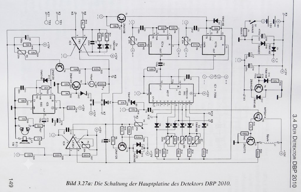
DBP 2010 Main PCB Parts List
Resistors (1% Metal Film)
| Reference | Value |
|---|---|
| R1 | 22 kΩ |
| R2 | 684 kΩ |
| R3 | 317 kΩ |
| R4 | 120 kΩ |
| R5, R20 | 5.6 kΩ |
| R6, R10, R17, R28 | 100 kΩ |
| R7, R9, R31, R33 | 10 kΩ |
| R8, R38 | 46.4 kΩ (see note below) |
| R11 | 22 kΩ |
| R12 | 40.7 kΩ |
| R13, R15, R21 | 56 kΩ |
| R14 | 8.2 kΩ |
| R16 | 12 kΩ |
| R18, R29 | 1.5 kΩ |
| R19 | 4.7 kΩ |
| R22, R30 | 330 Ω |
| R23 | 6.8 kΩ |
| R24 | 22 kΩ |
| R25 | 2.2 kΩ |
| R26, R27 | 825 Ω |
| R32 | 1 kΩ |
| R34 | 680 Ω |
| R35 | 47 Ω |
| R36, R38 | 1 Ω (see note below) |
| R37 | 39 Ω |
| R39, R40 | 100 Ω |
| R41 | 2.2 MΩ |
| R42 | 1.5 MΩ |
| RV | 820 Ω |
Potentiometers
| Reference | Value |
|---|---|
| P1, P2, P3 | 25 kΩ Trimmer |
| P4, P5, P6 | 25 kΩ Potentiometer |
| P7, P8 | 250 kΩ Potentiometer |
Capacitors
| Reference | Value | Type |
|---|---|---|
| C1 | 10 µF | Electrolytic |
| C2 | 2.2 nF | Ceramic |
| C3, C11 | 100 nF | MKT Polyester |
| C4 | 100 pF | Ceramic |
| C5 | 12 nF | Styroflex |
| C6 | 1 nF | Ceramic |
| C7 | 220 nF | MKT Polyester |
| C8 | 10 pF | Styroflex |
| C9, C13, C15 | 100 µF | Electrolytic |
| C10 | 12 nF | Ceramic |
| C12, C14 | 220 µF | Electrolytic |
| C16 | 4700 µF | Electrolytic |
Semiconductors
Diodes
| Reference | Part |
|---|---|
| D1–D11, D13–D17 | 1N4481 |
| D18 | 1N4001 |
| D12 | 8.2 V Zener Diode, 0.5 W |
Transistors
| Reference | Part |
|---|---|
| T1, T2 | 2N4124 |
| T3, T4 | 2N4126 |
| T5 | MPSA14 |
| T6 | 2N4403 |
| T7 | 2N3773 |
Integrated Circuits
| Reference | Part |
|---|---|
| IC1 | ICM7556IPD |
| IC2 | CD4017BCN |
| IC3 | LM741CN |
| IC4 | LF357N |
| IC5 | NE555CN (555CN) |
Other Components
| Item | Specification |
|---|---|
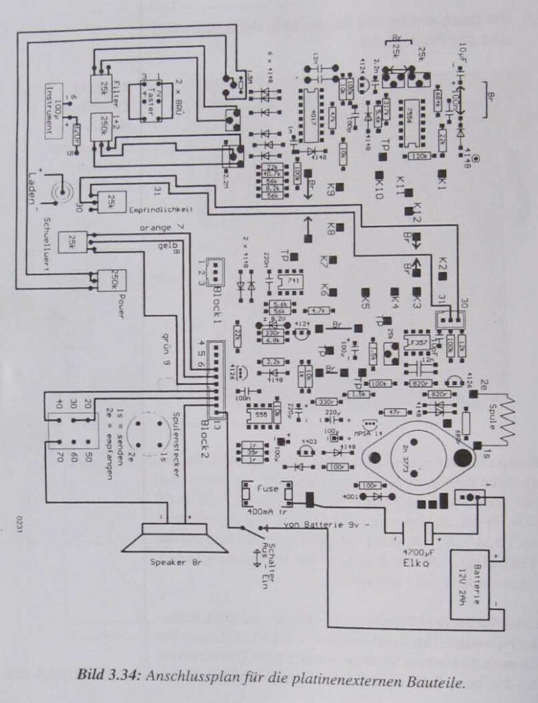
| Search Coil | See coil specifications |
| Power Switch | 1 × ON/OFF |
| Push Buttons | 2 × Momentary |
| Meter | 100 µA Analog Meter |
| Fuse Holder | For miniature fuse |
| Fuse | 500 mA |
| Headphones | High-impedance |
| Speaker | 8 Ω, 1 W |
| Battery | 12 V, 2 Ah |
| Header Connector | 3-pin |
| Header Connector | 10-pin |
Main PCB (without the module board)
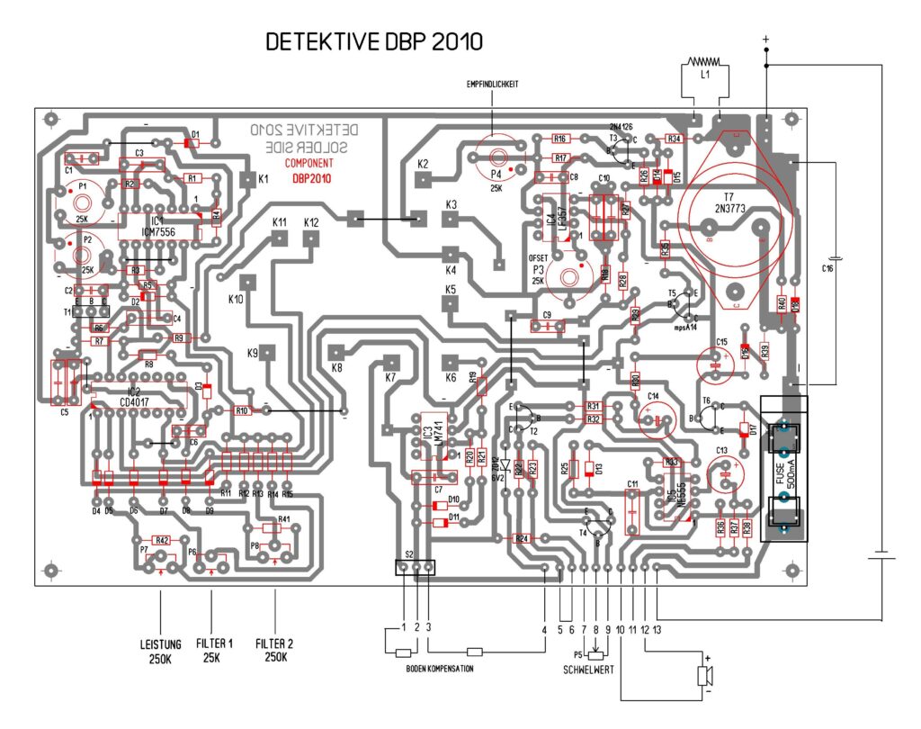
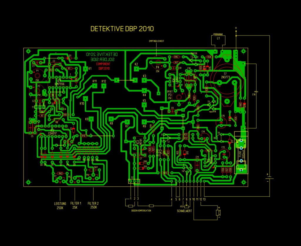
Errors correction:
- Transistor T4 (2N4126) – the collector and emitter are reversed.
- Transistor T5 (MPSA14) – the collector and emitter are reversed.
- R38 = 1 Ω should be replaced with 10–32 Ω.
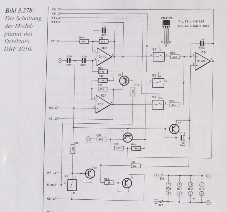
Module Board schematic
Module PCB (without the main board)
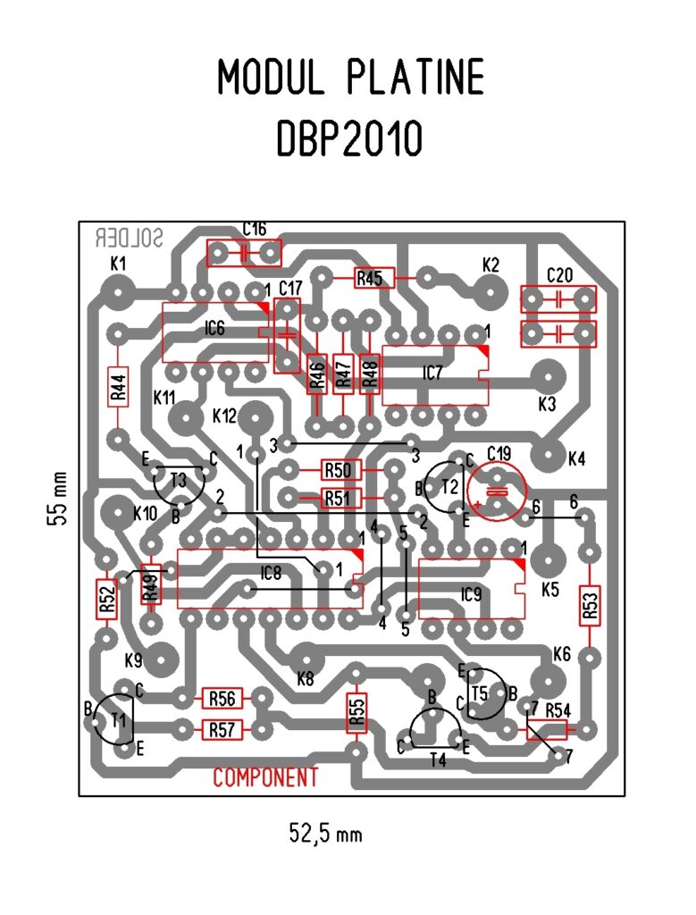
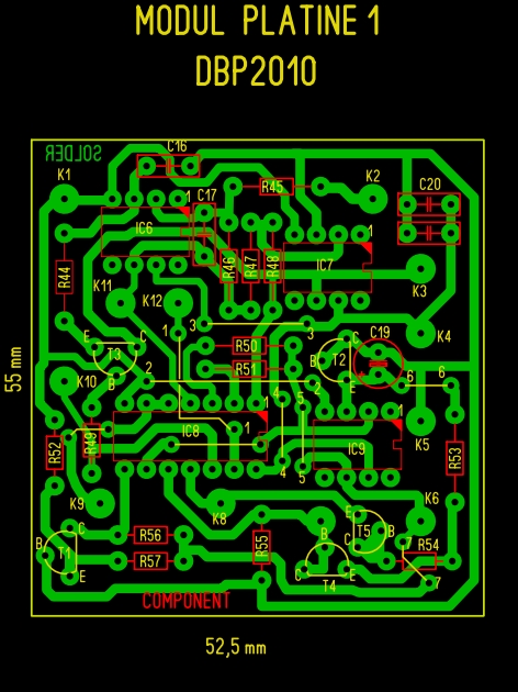
Errors correction:
- Transistor T3 – the collector and emitter are reversed.
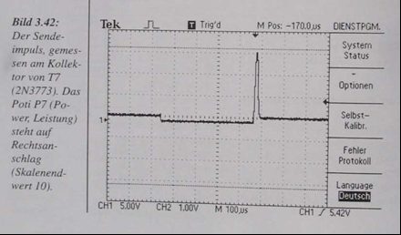
- R34 = 680 Ω in the original design (its exact value should be determined experimentally depending on the gain of T7 = 2N3773), so that the pulse signal at the collector reaches 130 V peak-to-peak when the “Leistung” (Power) control is set to 10.
Filters and Waveforms
Filter 1 should adjust the frequency from 290 Hz to 380 Hz:
- Position 0 = 290 Hz
- Position 10 = 380 Hz
Filter 2 should adjust the frequency from 380 Hz to 560 Hz:
- Position 0 = 380 Hz
- Position 10 = 560 Hz
Measured frequencies on the IC pins with the detector switched on and ready for operation:
IC1A
- Pins 2 and 6 = 60 Hz
- Pin 3 = 170 Hz
- Pin 1 = 2.2 kHz
- Pin 5 = 90 Hz
IC2
- Pins 8 and 12 = 280 Hz
- Pin 11 = 210 Hz
- Pin 9 = 650 Hz
T7 (2N3773)
- Collector frequency = 90 Hz
- Collector voltage = 130 V peak-to-peak
Figure 3.43 shows the received signal measured at pin 6 of IC4 (LF357) when both filters are set to position 10.
- Signal width: 580 µs
The received signal at pin 6 of IC4 becomes approximately 170 µs when a metal object is close to the search coil.
Circuit Operation Description
The transmitter signal is amplified at a switching frequency of 90 Hz by transistor 2N3773 (a replacement for 2SD551) to approximately 130 V peak-to-peak. It is then transmitted into the air through the search coil.
Proper damping of the search coil is achieved by R34 = 680 Ω, connected at the input of the coil, that is, at the collector of T7.
The switching frequency is generated by the first half of the dual timer IC1 (7556) and then doubled. It is used to set and reset IC2 (CD4017), which operates as a frequency divider and restores the operating frequency. Through transistor T5 (MPSA14) and 2N3773, it controls the transmission energy delivered to the search coil.
The second half of the dual timer IC1A (7556), together with operational amplifier IC3 (741) and the additional module board containing:
- IC6 = CA3140
- IC7 = IL709
- IC9 = CA3140
- CD4066
as well as five 2N4124 transistors, forms a timing control circuit with a built-in sample-and-hold function that measures and stores a reference value.
This section electronically compensates for the ground effect by measuring the ground’s capacitive characteristics and storing the reference value. The stored value is continuously compared with the received signal. This provides compensation for varying soil composition (minerals and ores) while allowing metallic objects to be detected independently of ground mineralization.
The detector operates by transmitting a pulse and then, after the timing sequence described above, switching to receive mode where it detects the signal reflected from metallic objects.
The received signal is applied to the input of IC4 (LF357). Thanks to the complex timing controller, the received signal is processed through a movable time window implemented by the LF357, allowing unwanted signals to be filtered out selectively.
The measurement window can be extended by using the frequency divider IC2 (CD4017).
The audio tone is generated by the LF357, together with IC5 (NE555) and transistor T3 (2N4126). The audio frequency is approximately 1.5 kHz.
Search Coil Specifications
Table 1 – Empirical Detection Range Results
Standard Search Coils
| Object | Material | Dimensions | DBP 2010 230 mm Coil | DBP 2010 430 mm Coil | VLF 770 230 mm Coil |
|---|---|---|---|---|---|
| Coin | Silver 800 | 40 × 3 mm | 32 cm | 39 cm | 36 cm |
| Wedding ring | Gold 750 | Ø 23 mm | 18 cm | 15 cm | 29 cm |
| Steel plate | St 52 | 100 × 100 mm | 68 cm | 87 cm | 60 cm |
| Bullet | Copper | Ø 20 mm | 45 cm | 61 cm | 48 cm |
| Hand grenade | Cast steel | Ø 50 mm | 61 cm | 75 cm | 51 cm |
| Jerry can | St 52 | 280 × 180 mm | 118 cm | 145 cm | 93 cm |
| Stamped part | Copper | 12 × 1.5 mm | 21 cm | 18 cm | 24 cm |
| Coin | Alloy | 1 Deutsche Mark | 20 cm | 16 cm | 25 cm |
| Jerry can | St 52 | 300 × 500 mm | 143 cm | 185 cm | 104 cm |
With Large Loop Coil and DBP 2010
Loop coil size: 1000 × 1000 mm
| Object | Material | Dimensions | Detection Range |
|---|---|---|---|
| Hand grenade | Cast steel | Ø 50 mm | 105 cm |
| Beverage can (Cola can) | Tin-plated steel | Ø 65 mm | 110 cm |
| Steel plate | St 52 | 100 × 100 mm | 115 cm |
| Steel plate | St 52 | 200 × 200 mm | 172 cm |
| Jerry can | St 52 | 280 × 180 mm | 225 cm |
| Steel plate | St 52 | 500 × 500 mm | 265 cm |
Search Coil Ø230 mm
- Diameter: 230 mm
- 43 turns
- Wire: 0.5 mm enamelled copper wire (CuL)
- Inductance: 858 µH
Search Coil Ø450 mm
- Diameter: 450 mm
- 23 turns
- Wire: 0.5 mm enamelled copper wire (CuL)
I hope this explanation has simplified, at least to some extent, how the filters operate and what is important to adjust in order for the detector to function properly.
The remaining information and detailed instructions can be found in the published book.
Download files
This content is available to logged-in users only.
هذا المحتوى متاح فقط للمستخدمين المسجلين.
Ce contenu est réservé aux membres connectés.
🔑 Login 📝 RegisterLog in or create a free account to access downloads and exclusive content.


