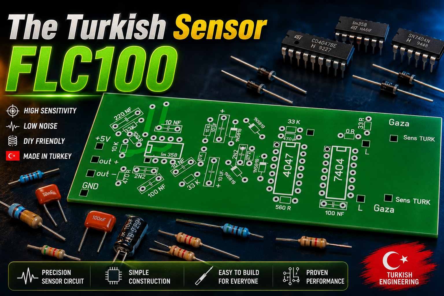
This circuit of Turkish Sensor FLC100 is designed for easy DIY assembly using through-hole (DIP) components, making it ideal for beginners and hobbyists. Start by soldering the resistors, diodes, and ceramic capacitors, followed by the IC sockets (recommended), electrolytic capacitors, and connectors. Finally, insert the LM358, CD4047, and 7404 ICs into their sockets, ensuring the notch on each IC matches the PCB silkscreen. Before powering the board, carefully inspect all solder joints for bridges or cold solder joints and verify the correct polarity of the diodes and electrolytic capacitors. This step-by-step approach helps ensure a reliable and trouble-free assembly.
Components list
| Reference / Type | Value | Qty | Notes |
|---|---|---|---|
| IC1 | LM358 | 1 | Dual operational amplifier (DIP-8) |
| IC2 | CD4047 | 1 | Multivibrator (DIP-14) |
| IC3 | 7404 | 1 | Hex inverter (DIP-14) |
| Capacitor | 220 nF | 1 | Film/Ceramic |
| Capacitor | 100 nF | 2 | Decoupling capacitors |
| Capacitor | 10 nF | 1 | Timing capacitor |
| Capacitor | 2.2 nF | 2 | Marked “2N2” |
| Capacitor | 470 pF | 1 | Ceramic |
| Electrolytic Capacitor | 10 µF | 2 | Polarized |
| Resistor | 10 kΩ | 2 | |
| Resistor | 33 kΩ | 2 | |
| Resistor | 470 Ω | 1 | |
| Resistor | 560 Ω | 1 | |
| Resistor | 33 Ω | 1 | Marked “33 R” |
| Resistor | 0 Ω | 1 | Jumper (marked “0 R”) |
| Diode | 1N5819 | 4 | Schottky diode |
| Power Connector | +5V | 1 | Input |
| Output Connector | OUT+ | 1 | Sensor output |
| Output Connector | OUT− | 1 | Sensor output |
| Ground | GND | 1 | Ground |
Printed Circuit Board
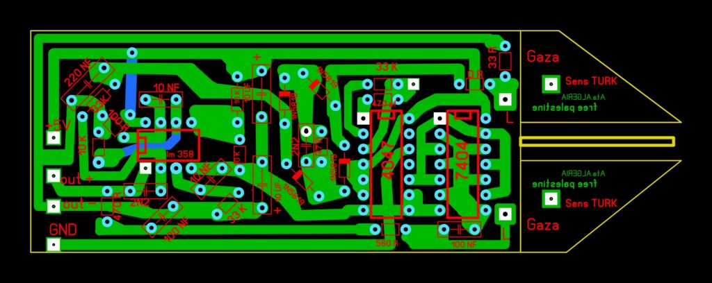
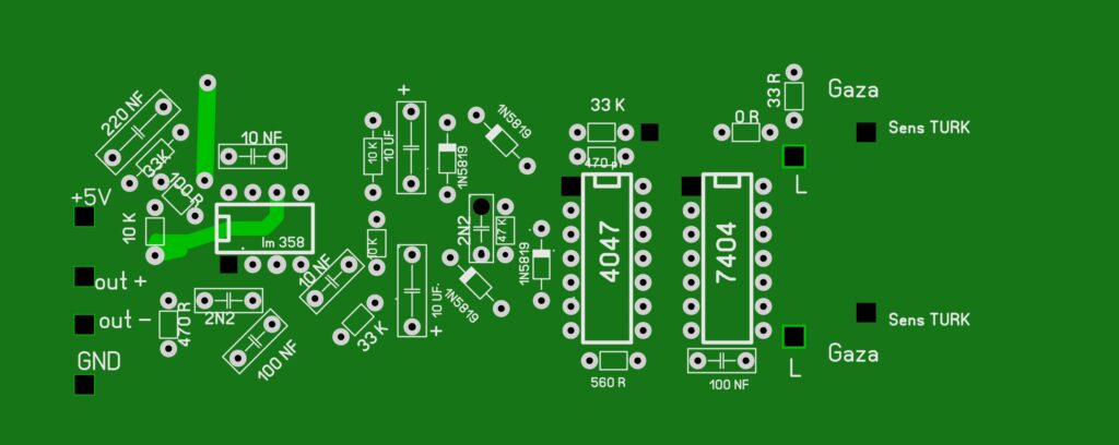
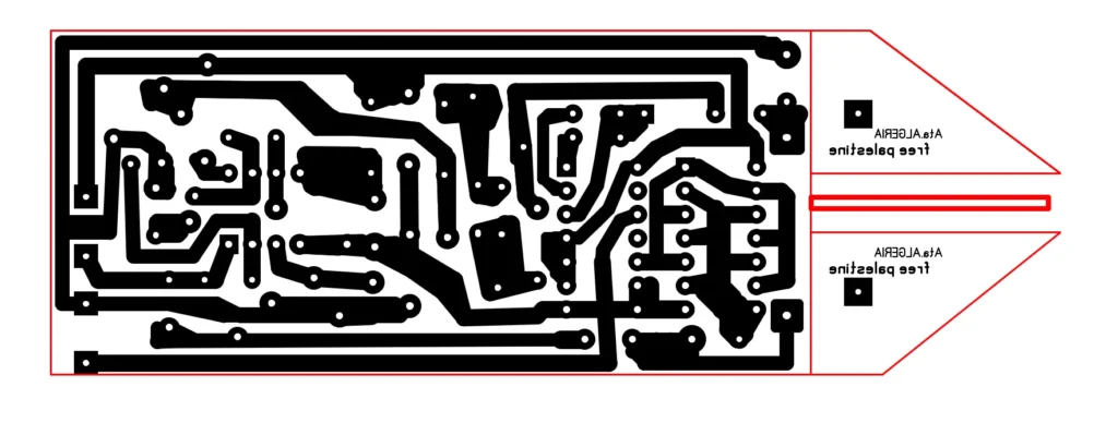
Download files
This content is available to logged-in users only.
هذا المحتوى متاح فقط للمستخدمين المسجلين.
Ce contenu est réservé aux membres connectés.
🔑 Login 📝 RegisterLog in or create a free account to access downloads and exclusive content.