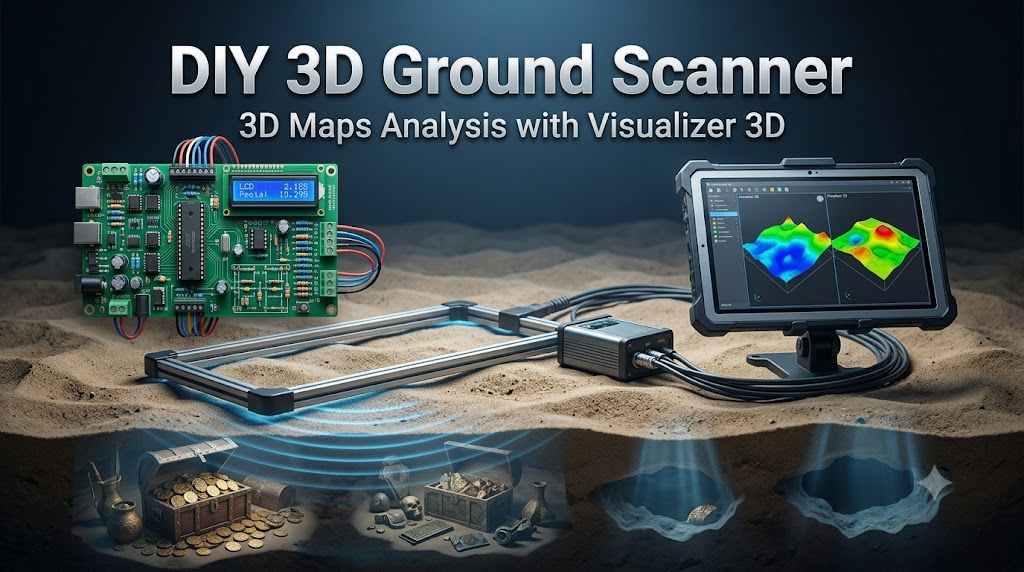
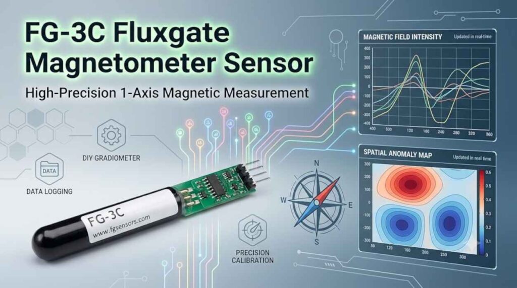
For many electronics hobbyists, the internal workings of professional-grade commercial sensors often feel like a “black box”—proprietary, complex, and frustratingly out of reach for the home workshop. However, that barrier is rapidly dissolving. High-end hardware like the FLC 100 or the industry-benchmark FG3 Plus are no longer shrouded in mystery. With access to the right schematics and modern fabrication tools, these devices have become accessible projects for any dedicated maker. Building a sensor that rivals commercial performance is no longer a matter of “secret” technology; it’s about mastering the technical blueprint and the electronic chain.

The Professional Edge of SMD and PCB Fabrication
If you want to move beyond basic prototyping into the realm of high-performance instrumentation, you have to leave hand-wiring behind. Professional-grade results require the precision of Surface Mount Devices (SMD) and custom PCB layouts. My primary tool for this is Sprint-Layout; it’s excellent for handling the specific Gerber files required by fabrication houses like JLCPCB.
While some hobbyists are still intimidated by SMD, these components are now the global standard and surprisingly easy to source. As the technical documentation for these professional designs notes:
“The pieces are listed inside the files and are easy to obtain.”
Transitioning to these professional manufacturing methods allows for a compact footprint and signal integrity that you simply can’t achieve on a breadboard or perfboard.
The Critical Choice Between Single and Double-Sided Designs
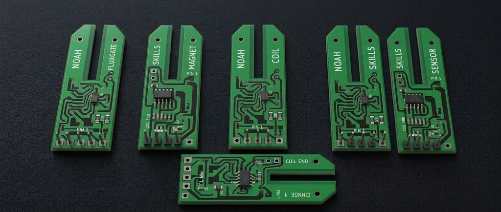
When you’re looking at schematics for a sensor like the FLC 100, you’ll often have to choose between a single-sided or double-sided PCB layout. Each has a specific use case depending on your workshop setup:
- Single-Sided PCBs: These are the gold standard for beginners or those who prefer home etching. They are much more forgiving when using Ferric Chloride (Iron Chloride) for chemical etching, as you only have to worry about one layer of traces.
- Double-Sided PCBs: These allow for the compact, “pro” form factor found in commercial units. However, be warned: double-sided Gerber files exported from Sprint-Layout often require manual re-editing and modification before they are ready for a professional manufacturer. If you are etching these at home, you must ensure perfect registration between layers and manually solder vias to link the top and bottom connecting points.
For your first few builds, a “Single Side” version of a commercial schematic is often the most practical route to a working sensor.
The “Magic” of the Amplification Circuit
The most common mistake I see is builders focusing solely on the sensing element. In reality, the range of your device is determined by the “completeness” of the electronic chain—specifically the amplification stage.
Using a high-quality amplifier like the TLV 272 can radically transform your hardware’s performance. For example, a sensor integrated with an Arduino might only reach a range of 5 meters on its own. However, by adding a dedicated amplification circuit, that range can jump to 8 or 10 meters. It’s important to understand the modularity here: for an Arduino setup, you generally need a separate amplification board for each sensor. In contrast, other designs (like the Conrad) are engineered to run two sensors off a single amplification board. As the source material emphasizes:
“Every piece completes the other.”
The Sensitivity of Coil Calibration
In the world of high-end sensors, professional doesn’t mean “one size fits all.” You might see two “identical” FLC 100 units with different component values, and there’s a technical reason for that: coil calibration. Capacitor values are directly linked to the specific induction and resistance of the coil you’ve wound.
Since DIY coils are rarely identical, you must be prepared to fine-tune your periphery components. This often involves swapping out capacitors or selecting specific operational amplifiers. While the OP291 is a common choice for these designs, don’t feel locked in—it is interchangeable with other high-quality amplifiers depending on your specific needs and the analog sensitivity you’re aiming for.
The Logic Core: Why 4047 and 7404 are Non-Negotiable
While the “periphery” of the circuit (amplification and coils) requires constant adjustment, the “core” logic of these sensors is remarkably stable. Regardless of the brand or model, you will almost always find two specific Integrated Circuits (ICs) at the heart of the design: the 4047 and the 7404.
These ICs serve as the “constants” of the sensor’s architecture. They handle the fundamental timing and logic—the digital heartbeat of the device—while the variable amplification stages handle the sensitive analog work. Having this stable core allows you to experiment with different coils and amplifiers without worrying about the underlying logic of the sensor failing.
Conclusion: The Future of Your Workbench
The journey from downloading a Gerber file to achieving a 10-meter detection range is now a reality for the modern DIYer. By embracing professional PCB fabrication, understanding the nuances of Ferric Chloride etching, and mastering the synergy between your IC core and amplification stages, you can build hardware that stands toe-to-toe with commercial units.
As we gain more access to high-end designs like the FG3 Plus, we have to ask: has the gap between “commercial” and “DIY” finally vanished? Looking at the professional depth and range we can now achieve at a soldering station, it’s clear that the “black box” is officially open. It’s time to start your next build.