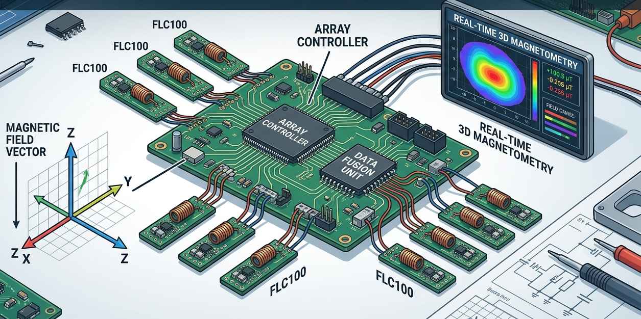
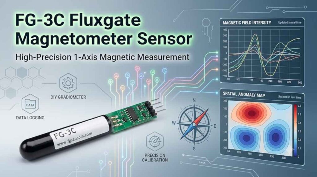
The FLC 100 sensor is one of those devices that generates a lot of questions — particularly about the differences between manufacturers, the coil values, the circuit diagrams in circulation, and why not all versions give the same values even though they all serve roughly the same purpose.
The key idea to understand from the start is that the sensor’s name or outward appearance isn’t enough to judge its value. You might find an American-made sensor, a German one, and a Turkish one, all similar in principle, but each company’s circuit is built around a different IC and a different frequency-setting capacitor — which is why the coil’s value and resistance change from one to another.
Don’t Print the Two-Sided Board As-Is
Some of the published FLC 100 diagrams are meant for hand-etched/hand-printed boards, and some of them are laid out as two separate sides. That doesn’t mean the file is ready to be uploaded directly to PCB manufacturing sites like JLCPCB.
The problem is that a diagram meant for hand printing doesn’t necessarily include the board outline and layer arrangement required for automated manufacturing. If you print the two sides exactly as they are, you’ll still be left with the problem of aligning the two boards and connecting them precisely.
For anyone who wants to order a board from a factory, there are two better options:
- Redraw the second side underneath the first side and properly set up the design as a correctly formatted double-layer board.
- Choose a single-sided layout using flat SMD components, since that’s easier to manufacture and assemble.
The two-sided design as it’s commonly shared is better suited to hand printing, not to ordering directly from a factory without modification.
Why Do FLC 100 Sensor Values Differ Between Manufacturers?
The fundamental difference between commercial sensors isn’t just in shape — it’s in the electronic IC used and in the frequency-setting capacitor. When these two components change, the coil’s inductance and resistance change along with them, so that the frequency of the coil-and-capacitor circuit matches the frequency of the electronic circuit.
In simple terms, you can’t take the coil from a German sensor and drop it randomly into an American sensor’s circuit and expect the same result. The coil is part of an integrated system that includes the IC, the resistors, the capacitors, and the frequency circuit.
That said, most sensors give fairly similar results when every part matches its own diagram. So don’t let a difference in brand name stand in your way — build whichever sensor you can source the parts for, and whose coil you can wind to the correct values.
The American Sensor and the German Sensor
There are diagrams for both American-made and German-made sensors, and each has its own layout and its own values. Turkish sensors are similar in origin to the American sensor, with some minor differences in certain values.
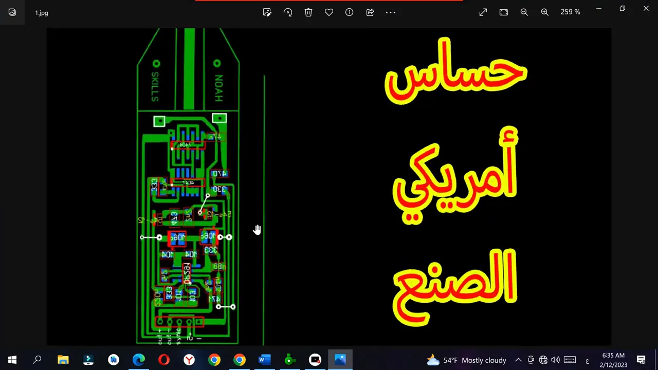
The American version uses a different board layout and coil values matched to its own circuit.
The German version is one of the well-known variants, and its coil values have been published as follows:
- Coil inductance: 10.4 mH
- Coil resistance: 38 ohms
These values are specific to the original German sensor, so they should be followed exactly when building its circuit. They should not be treated as universal values for every FLC 100 sensor.
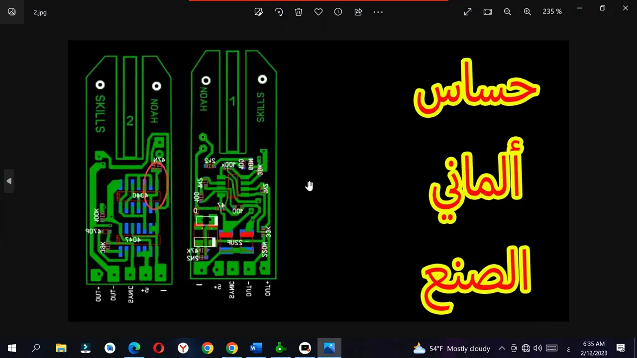
The German sensor uses a different layout and has its own distinct coil values.
As for the Turkish sensor sold by some companies, its coil value is generally cited as around 550 µH, with a resistance of about 5.5 ohms. These values differ significantly from the German version, but that’s not a mistake — it’s simply a natural result of the different circuit and IC being used.
The IC and the Frequency Capacitor Are the Key to Choosing the Coil
Companies use a range of different ICs in these sensors, and depending on the design, you’ll see either common ICs or various alternatives. One example that appears in some versions is the AD8617 IC, alongside other ICs that vary by manufacturer.
When the IC or the frequency capacitor changes, the operating conditions of the resonant circuit change too — and so the coil’s inductance and resistance must change accordingly. This is why there’s no single value that works for every coil in every sensor.
The practical rule is:
- First, settle on the specific sensor diagram you’re going to build.
- Stick to the IC specified in that diagram.
- Use the same resistor and capacitor values given in it.
- Wind the coil to the exact inductance and resistance specified for that diagram.
Following this approach gives you very consistent results across different versions, instead of mixing parts from several designs and running into endless calibration problems.
Some Versions Differ More Than Others
There are sensors in which a large number of values have been changed — including the resistors, the capacitors, and the coil itself. These versions can perform well, and some may even outperform certain sensors on the market, but the drawback is that they become harder to source parts for.
For that reason, I don’t recommend overcomplicating things. If you already have the parts for the American sensor, it’s a good and straightforward option. What matters most is building it completely according to its own diagram, and matching the coil to the values it requires.
Understanding How the Coil Works Before Trying to Calibrate It
The coil isn’t just an extra component in the sensor — it’s the foundation of how the device works. The goal is to generate a low frequency, then pick up on the very brief change that occurs in that frequency. So it’s not enough to just transmit a signal; the circuit also has to be able to receive and analyze the response quickly.
Lower frequencies penetrate rock relatively directly, unlike clay-rich soil, which affects how the signal behaves. In practice, though, this isn’t really about how far the signal travels through open air — it’s about the circuit’s ability to pick up the subtle changes caused by the surrounding medium.
The Role of the Carbon-Free Metal Piece
Some sensors use a piece of carbon-free metal to fine-tune the coil’s inductance, and by extension, its frequency. Changing the size of this piece affects the coil’s inductance while keeping its resistance roughly the same.
Suitable metal can be salvaged from transformer laminations or from parts of a soldering iron, but the pieces sold specifically for this purpose remain a more reliable and consistent choice than improvised alternatives.
This piece doesn’t do anything mysterious — it’s simply a way of tuning the frequency of the coil-and-capacitor circuit so that it matches the oscillator frequency of the electronic circuit.
Replacing the Metal Piece with a Variable Resistor
In some designs, the carbon-free metal piece can be omitted entirely and its role replaced with electronic tuning instead. The idea is to replace the fixed 39 kΩ resistor — connected between pins 2 and 3 of the 4047 IC — with a 50 kΩ variable resistor (potentiometer).
You then gradually adjust the variable resistor until the IC’s frequency matches the resonant frequency of the sensor coil. This method makes the matching process easier, especially when using easily available DIP components.
That said, this adjustment needs to be done carefully and precisely. The variable resistor is not a substitute for a poorly wound coil — it’s only a tool for fine-tuning at the end, once the coil’s inductance and resistance are already close to the required values.
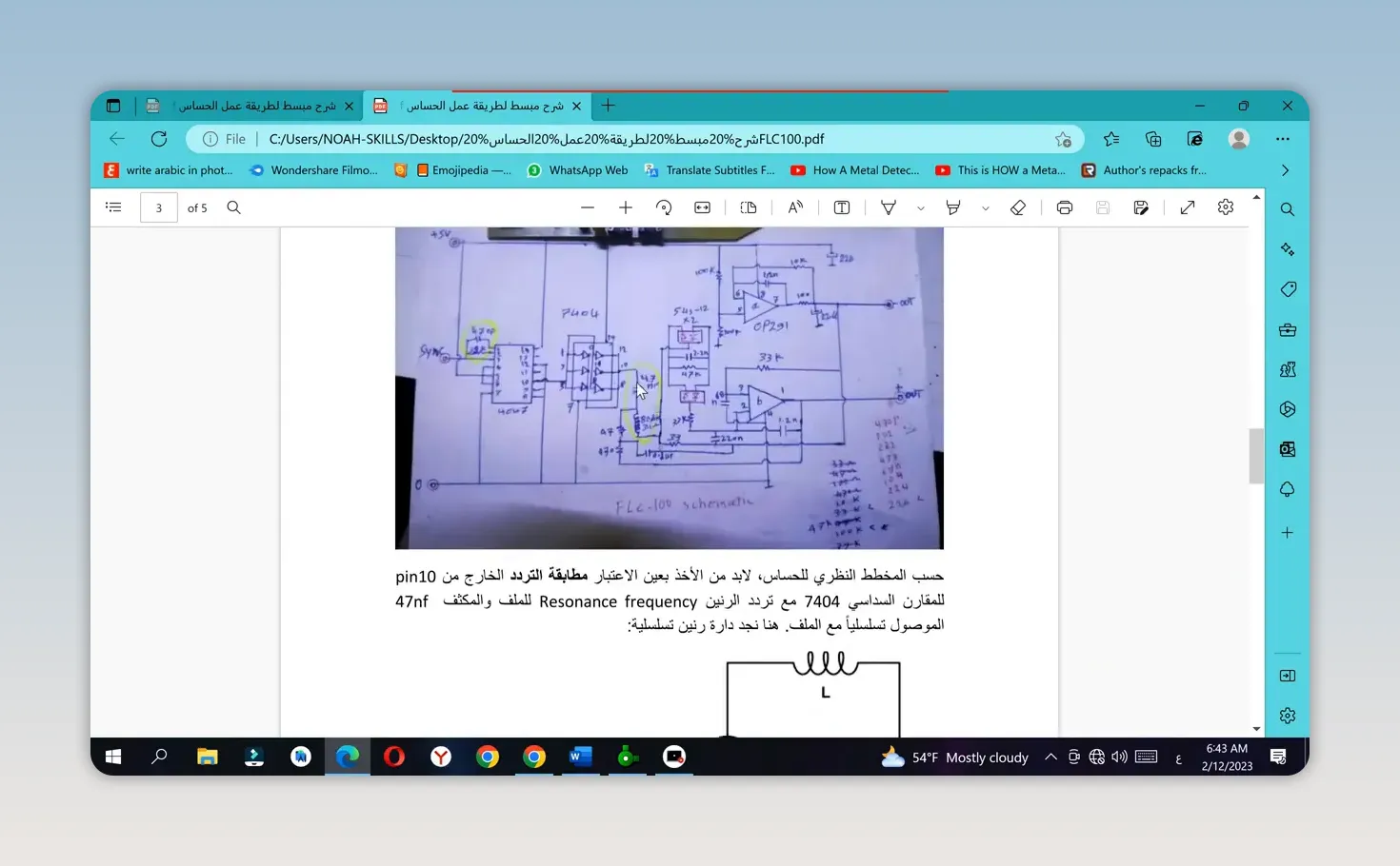
Matching the coil to the frequency circuit starts with understanding the diagram and how its components relate to one another.
What Actually Matters in Imaging-System Devices?
In devices that rely on an imaging system, the device itself isn’t what determines the result. What matters far more is:
- The sensor — its design quality and how well its coil is tuned.
- The amplifier circuit — and how well it’s matched to the sensor.
If the sensor isn’t properly calibrated, or the amplifier circuit isn’t well matched, the problem won’t be solved just by changing the screen or adding cosmetic features to the device.
Choosing a Sensor You Can Actually Build
The goal isn’t to chase the hardest sensor to build or some rare version — it’s to build a complete, working version using parts you can actually get. The American sensor is a good option in terms of ease of manufacturing, and the German sensor is also a solid choice as long as its coil is wound to the correct values.
Make sure to prepare your sensors and their coils in advance, since the success of any later device depends first on how well the sensor matches the amplifier circuit and the overall electronic circuit. Understand the values, follow the diagram, tune the frequency carefully, and — God willing — you’ll get good performance without having to pay inflated prices.