We present to your attention the third modification of the Tracker FM metal detector.
The primary objective in developing this design was to minimize the effect of soil on the search process and to improve ease of use. This was achieved through the following design solutions:
- Using a relaxation generator with minimal oscillation amplitude, which has shown sufficient efficiency on real soil.
- Introducing an intermediate signal amplifier.
- Using a dynamic operating mode.
- Eliminating LED indication in favor of a loud, clear sound.
The generator and dynamic operating mode used allow us to minimize the soil’s influence on the search coil (by reducing the earth’s residual magnetization) and to cut off harmful interference.
The modified power supply circuit (the generator, amplifier, and microcontroller are all powered at 3V) allows for increased operating life from a single Krona battery without any degradation in device performance.
This upgrade can be considered the optimal option for a frequency-based metal detector for use as a primary search device (taking into account its actual characteristics, of course).
Sensitivity:
- Coin, D = 25mm: 15 cm
- Small infantry shovel: 40 cm
Technical solutions used in this modernization:
Schematic diagram
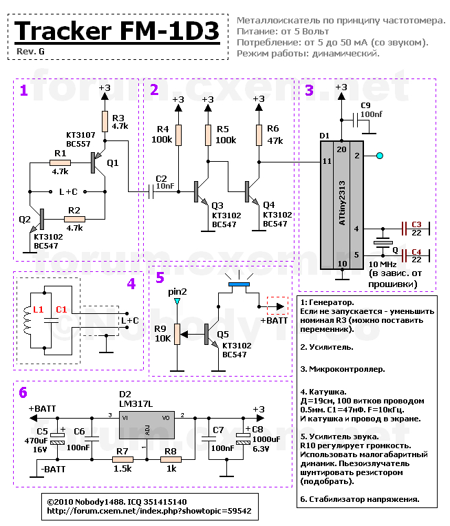
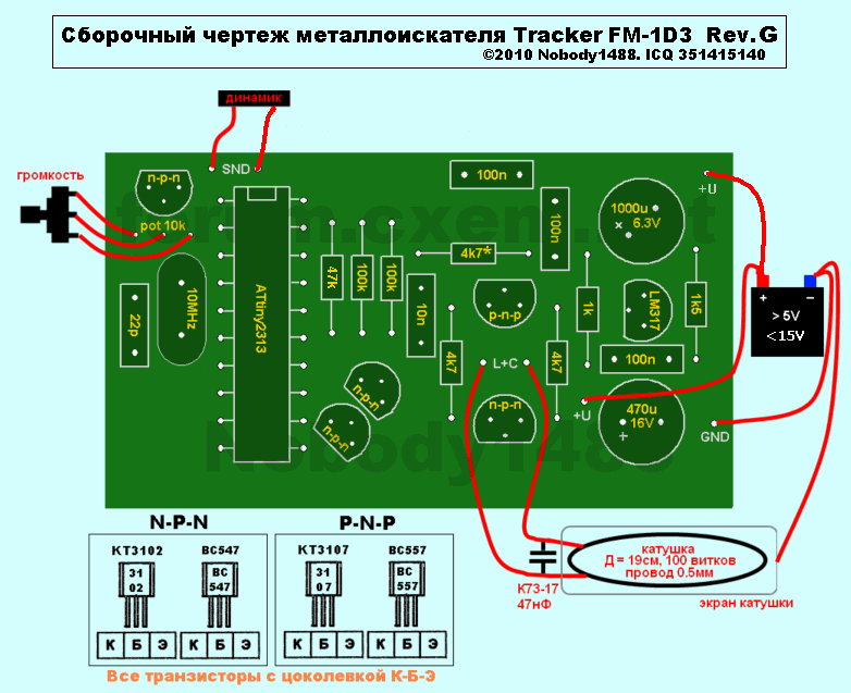
Generator:
It is built using a resonant oscillator circuit that operates at the natural frequency of the L1C1 tank circuit. The main advantage of this design is its frequency stability across a wide range of supply voltages, and its ability to connect the circuit’s capacitor directly to the search coil. This eliminates any influence of the sensor-to-circuit wire on the circuit’s frequency.
Signal booster:
This stage accomplishes two things at once: amplifying the generator’s weak signal, and converting it into a form suitable for processing by the microcontroller. In this way, weak sine waves are transformed into something closer to “digital” pulses, with steep rising and falling edges.
Microcontroller:
As with the original circuit, the microcontroller handles all signal processing. Specific functional features may vary depending on the firmware:
- 1D3boost — a modified version of the original firmware. Dynamic mode is retained. All adjustment options have been removed. Buttons are not used. A sound bug has been fixed.
- 1D3boost+ — firmware with increased sensitivity. Recommended for quiet, interference-free environments and soft soil conditions.
Voltage stabilizer:
Implemented using the LM317 integrated voltage regulator, with an output voltage of approximately 3V. Filter capacitors improve the stability and quality of the power supply throughout the circuit.
Search coil (sensor):
It consists of an inductor coil and a film capacitor connected in parallel. A two-conductor shielded cable is soldered to them, with the other end soldered to the board. The coil is enclosed in a foil shield using a well-known technique. This shield is soldered to the cable’s shielding, which in turn is soldered directly to the negative terminal of the power supply. If you plan to use a disassembled design, or want to build several coils of different diameters/frequencies, you can connect the coil via a connector — just make sure it provides good, durable contact.
Recommended coil parameters:
- 100 turns of ~0.5mm wire wound on a 19 cm diameter mandrel.
- A 47nF capacitor (type K73-17, or the most thermally stable one available) soldered directly to the coil terminals.
Indication:
It’s best to rely solely on audio indication, since in real search conditions it’s impractical to constantly watch an LED indicator. For this reason, an audio amplifier has been added to the circuit, allowing for a significant volume increase. The maximum achievable volume depends on the type of speaker used and the battery voltage.
Setup procedure:
Once the board is fully assembled and all wiring is in place, power on the device. If everything is working correctly, you’ll hear a short beep from the speaker, after which the device will enter operating mode. If the speaker instead emits a continuous tone, the analog section of the circuit (oscillator, amplifier) has not been assembled correctly.
Most likely causes of malfunction (assuming no assembly errors):
- Resistor R3 has too high a resistance for the coil you’re using. The circuit is designed to operate with a 10 kHz search coil. If the frequency drops below a certain threshold, the generator will stall. Try adding an additional 10 nF capacitor at C1. If the device starts working, you can either leave the extra capacitor in place, or remove it and reduce the value of R3 instead. Keep in mind that R3 should be as high as possible while still allowing the device to operate correctly.
- The speaker or piezo buzzer is faulty (or of the wrong type). In this case, a properly functioning device may appear completely “dead.” Replace the speaker or buzzer if there is no sound, but a beep signal is still present on pin 2 of the microcontroller.
ATTENTION! There are reports of poor performance with this device on real soil. Weigh the pros and cons carefully before assembling it!


