Nowadays, when interesting search locations have been largely eliminated, the most pressing concern for metal detecting engineers is improving the efficiency of their devices and their competitiveness when working in a team whose comrades are equipped with top-of-the-line detectors from well-known brands. How can we help our devices detect deeper, more reliably, and more selectively? The circuits themselves are usually already perfected and cannot be significantly modified. Editing the firmware of amateur digital detectors is only available to their creators. That leaves the sensor. Many believe that everything has already been exhausted in this regard: a concentric sensor for trashy areas, a DD “steering wheel” for quickly combing vast spaces, and that’s it.
What’s the main problem with metal detecting with a metal detector? Overcoming the effects of soil. Only in this area (by helping the device combat thick, sometimes heavy, soil) can one hope to look respectable with a homemade device, and even gain an advantage over owners of expensive, commercially available modern detectors.
In this thread, I’ll present my experience building two sensors that differ from the traditional “concentric sensor” and “double-D” sensors. Both models are designed specifically for more effective ground control and, therefore, for both greater target detection depth overall and greater reliable VDI (i.e., improved non-ferrous target rejection in heavy soil, including heavy soil).
The Omega
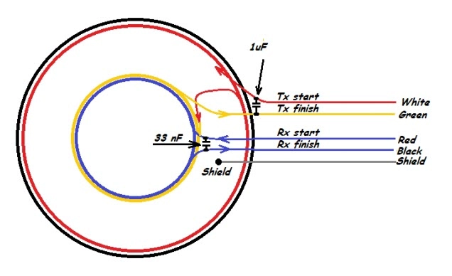
is an alternative to the concentric sensor, which features a “spot” (or more accurately, “cone”) beam pattern, making it attractive for use in trash-strewn areas. The main drawbacks of the concentric sensor are well known: it performs poorly in heavy soils (since the IB balancing is done electrically, not physically, differentially), and is difficult to set up (three coils, a loop, etc.). This is where the concentric sensor’s “cousin” – the Omega – comes into its own. The name derives from the similarity of the coil arrangement in this sensor to the Greek letter Omega. Balancing is differential (meaning it will perform better with soil); there are only two coils, without selecting turns or changing the loop configuration, which tends to overfit the existing housing geometry, etc. As is known, some companies previously produced Omega sensors for their devices. The idea was later abandoned because winding a transmitting coil is very difficult to manufacture and practically unsuitable for mass production. Some 10-15 years ago, hobbyists tried making such sensors, but the poor performance of the devices of that time prevented them from being fully appreciated.
I’d long wanted to try making an Omega, but the lack of ready-made molds for this size prevented me from realizing my dream. Everything changed when I came across this housing (a cast one at that) for a small DD sensor. Its lower section begged to be used for a receiving coil and the “squiggly” shape of a transmitting coil. A trial winding, tuning, and benchtop testing showed that it was feasible.


The transmitting coil was then rewound to the optimal “squiggle” shape for placement in this housing. Since a heavy cast housing was used, the voids were filled with foam as much as possible.

Ground testing showed identical performance (in terms of “VDI reliability for deep-lying non-ferrous targets”) between the O20 and the K25 concentric sensors under otherwise equal conditions, meaning the Omega clearly outperforms. The O20 itself was tested on the ground in the 9-17 kHz frequency range and with various pump currents. Both performed reliably.

Design. The ratio of the diameters of the receiving and transmitting coils is the same as in a concentric sensor (1:2), the number of turns and the wire diameters are also taken as for the “ring.” To make the transmitting coil: using a thread in the housing, we measure the length of the transmitting coil with its balancing “squiggle,” laying it out in the housing as it will look. Then we wind a regular “round” coil of the measured circumference; after fastening the turns, we bend the “squiggle” to the desired shape. After preliminary tests (to ensure everything comes together), the transmitting coil is completely cast in its original place in the housing. It is highly desirable that a smooth, flat “platform” forms above the “squiggle” where the receiving coil will subsequently be located. Separately from the transmitting coil, outside the sensor, the receiving coil is impregnated with epoxy and placed on a flat surface to harden. After drying, it’s a good idea to artificially age both halves of the sensor (using the standard “heat-cold” method). After a few days, assemble the sensor. Place the round receiver coil over the “squiggle,” achieving the desired final imbalance, correct target response, etc. Glue the coil securely in place with superglue (gluing to the same “pad” above the “squiggle”). Let it sit for 24 hours. Check the balance and completely fill the sensor with the final coating. Both coils are impregnated and aged, the receiver coil is securely glued in place—there will be no imbalance shift whatsoever. Let it dry, then proceed as usual—final graphite coating, etc. If the first attempt is a flop, or something goes wrong, the Omega can easily be “brought out of its stupor” with a piece of ferrite. But this won’t be necessary.
The challenges in constructing the Omega are obvious: the lack of ready-made casting molds and the “two-tier” design (one coil is located above the other, increasing the thickness of the sensor). The first problem is a no-brainer for those accustomed to making sensors in foam or prefabricated disk-shaped housings without holes. The second problem is easily solved if you remember how the two windings of a DD sensor are positioned at the intersection of one coil above the other—a special “groove” in the sensor housing, which “flattens” the entire structure and saves on materials and weight.
Let’s consider a couple more nuances of the Omega’s design. They concern the size of the balancing “squiggle” of the transmitting coil. The relationship is as follows: the larger the diameter of the “squiggle,” the more the round receiving coil must be offset toward the center of the sensor to achieve the desired balance. To position the receiving coil at the bottom of the sensor, I had to size the “squiggle” so that it was centered on the receive coil, with approximately 1.5 cm of space between the coils on all edges. Naturally, the sensor’s maximum sensitivity is at the “common center of mass” of the coils, meaning the polar pattern of my sensor is slightly offset downward from the center. If you want the center of sensitivity to be as close to the center of the sensor as possible, the diameter of the “squiggle” is equal to the diameter of the receive coil. Of course, in a balanced sensor, the receive coil will also be closer to the center. Here are a couple of photos related to this, found online:

Super D coil
The next craft was inspired by Minelab’s powerful advertising of its new GPZ 7000 gold prospecting sensor.
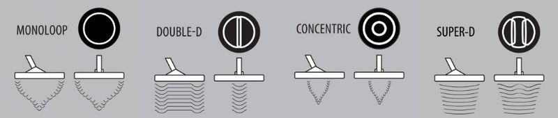
No implementations of this type of sensor by amateurs (at least, no publications about it) have been found on the Internet. Having looked closely at the sensor’s design and its properties, it is simply impossible not to build one))) Judge for yourself: a “rudder” that, due to increased differential subtraction, copes better with the ground; plus, due to a wide and uniform radiation pattern, it will not miss even the smallest targets, no matter how fast you scan.
The disadvantages of a conventional DD sensor are well known: side lobes in the radiation pattern; scanning the ground with a wide strip “along” but a narrow “outward” one, which can lead to missing a small target with sufficiently fast sweeps or when using high-speed filters. The Super D sensor, on the other hand, due to its overall symmetry and division of the receiving coil into two equal parts, allows for even more differentiated combat with the ground; It has a broad directional pattern in all directions—the target response is unusually long and will not go unnoticed even for the smallest targets. This, of course, also has its drawback: the sensor is unsuitable for trash-strewn areas. It’s the “king of fields” where targets are located quite far from each other in the ground; soon, it will become a favorite sensor for hunters of small, rare artifacts of the deepest antiquity—Skifs, ChK, KK, PK, KR…
The sensor’s design is clear; the problem, as with the Omega, is practically the same: a lack of ready-made casting molds. So, I’m choosing from what’s available. I liked the M30 housing for a mono-sensor for a pulse generator. Trial winding, alignment, and calibration showed that everything was feasible. After refining the final geometry of the receiver coils, they were rewound with 0.18 gauge wire (the photo shows trial receiver coils with 0.14 gauge wire “because I have a lot of it”))) Then everything was as usual: alignment, casting in several stages, with thermal shocks, graphing, etc.

Field tests were conducted with equal input conditions, alternating with the DD32x30 sensor. The newly manufactured SD30 sensor demonstrated consistent superiority in all tests, except, naturally, the target separation test. Due to its superior ground resistance, several centimeters of improvement were achieved in the “VDI reliability of deep-seated non-ferrous targets” and “maximum detection depth of ferrous metal targets.” The SD30 sensor itself was tested in the 6-12 kHz frequency range at various pump currents, including the highest ones. Both conditions held up very well.

Manufacturing nuances. First, how do I calculate the coil sizes, proportions, and relative positions? I printed out a photo of a branded sensor, drew lines to scale with my enclosure (15 cm – half), and got the approximate geometry. Then I roughly scraped it and re-glued the existing casting mold to the desired configuration. Coils: the number of turns and wire diameters are the same as for a regular DD sensor, only we wind the receiving coil “in half” – the number of turns for each part. Then we connect these coils in series. We cast the transmitting coil directly in its native location in the enclosure. Balancing this sensor is a pleasure – balancing is soft and smooth (the receiving coil is divided in half – balancing in the “millivolts-millimeters of space” ratio is twice as smooth). Each half of the receiving coil has its own convergence zone; if you screw up on one side, the other will fix it))) Although, of course, it is desirable to maintain maximum symmetry of the sensor, so that its left side mirrors the right.
So, it’s clear. If the intention is to make a sensor in a ready-made housing, then there’s no other choice—concentric or double-D. If, however, the intention is to make a sensor in foam or a ready-made “flying saucer”-type housing (where the coils can be arranged in any shape), then why not try something that goes beyond the generally accepted form factors? Moreover, this would provide advantages in search and even, in some places, simplify the overall manufacturing process. We hope that in the near future, our “plastic blowers” will also join the fray with offers of ready-made casting molds for such things.