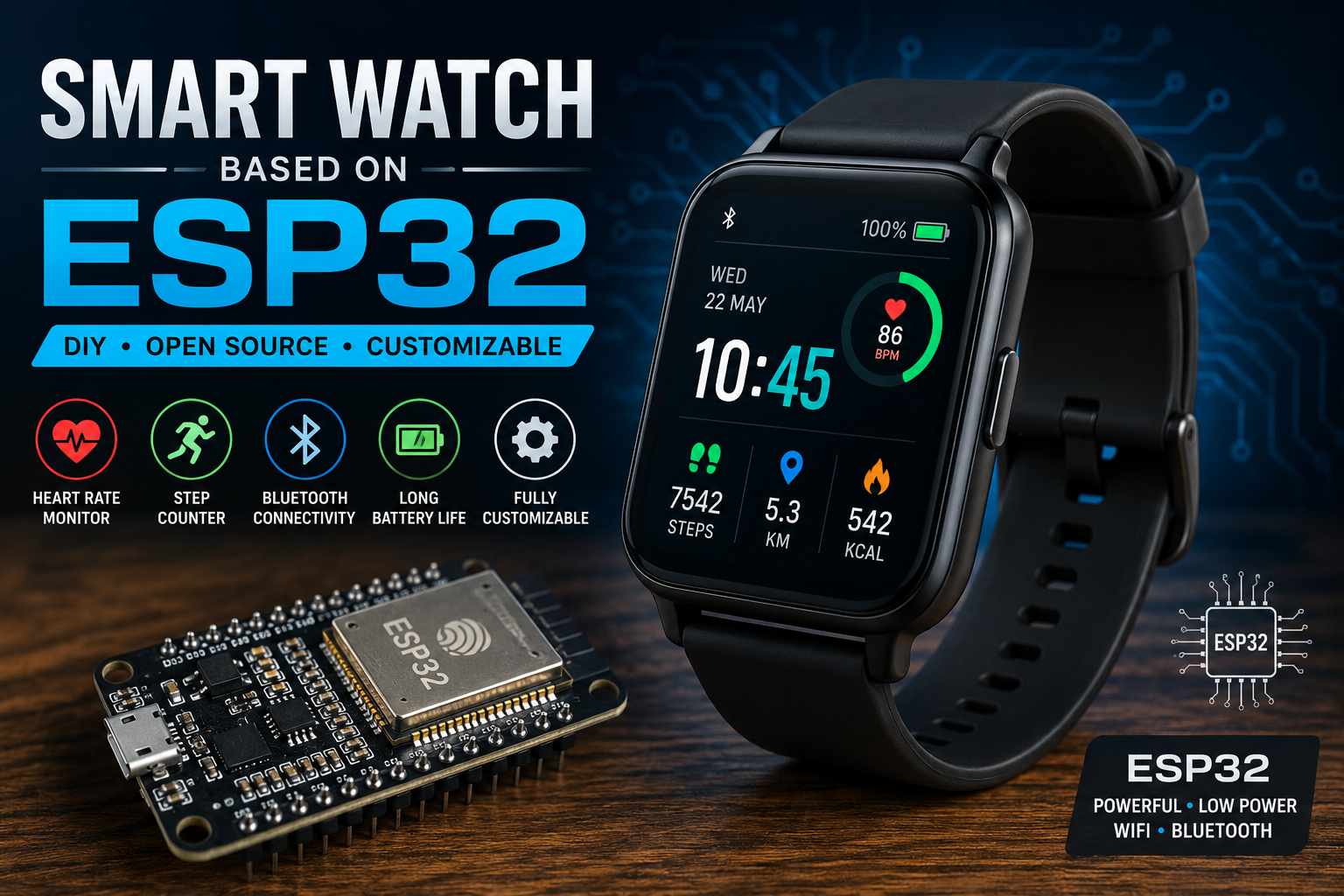
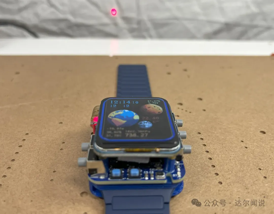
This is a very complete open source smartwatch project with complete functions and open source data. If you are: an engineer who likes DIY, a student who wants to improve his development skills, or a senior who is about to do a graduation project, this watch is worth making. Don’t miss it~~
All open source materials and original links are at the end of the article.
Let’s first look at the functions of this watch:
First, it is a watch that can be worn
Can act as a compact wireless access device to control all IoT devices
Also has the ability to exchange MAC addresses and scan WiFi networks
Built-in distance sensing LiDAR
Real-time temperature, altitude, humidity, pressure, gas, tilt and acceleration
All operations controlled by buttons
Main functions explained
Distance measurement: The LiDAR used is the super-compact VL53L1X ToF (Time of Flight) distance sensor from STMicroelectronics. It has an accuracy of <±1% and can measure any distance from 4 cm to 4 m. Since it uses a 940 nm laser (which is infrared and therefore invisible to the human eye), a switchable bright red 650nm 5mW laser is also included next to it to help with aiming or demonstrations.
Wireless part: The watch uses ESP-NOW to broadcast data quickly with ultra-low power consumption. This wireless protocol was chosen because it is able to bypass the traditional WiFi connection setup, which makes the reaction time between actions of other devices almost instantaneous and suitable for most 32-bit MCUs.Scanning WiFi Networks:The watch can also be used to scan for WiFi networks and provide the network SSID, RSSI (signal strength) and authentication mode (security of the network 0-7).Since broadcasting wireless data is very power-hungry, the watch is programmed to only activate WiFi temporarily to send/receive data, then automatically disable. It also has an automatic 1.5 second sleep mode timer and tilt-to-wake detection, much like the Apple Watch, which can’t be connected to a DIY door lock/light switch.Digital Level/Slope Detector: Simply place the watch on the surface in question and click the IMU mode button to access real-time tilt and acceleration data.Air Monitoring: The watch’s built-in Volatile Organic Compound (VOC) sensor observes changes in IAQ readings as the target gas comes into contact with the BME680’s heated metal oxide layer, and also monitors humidity and atmospheric pressure.Theme modification: The watch also comes with multiple themes, you can choose your favorite color.
Now that the functions have been introduced, let’s take a look at how to start from the schematic diagram——
The main circuit consists of the ESP32-S3, five sensors (optionally a sixth), a LiPo battery, a laser module driver, and typical circuitry for powering, communicating, and setting up the ESP32-S3 microcontroller, as well as some buttons and connectors. Here is the complete schematic:For a more detailed schematic diagram, see here: https://www.roboticworx.io/p/build-custom-esp32-boards-from-scratch#%C2%A7the-schematicTo fit so many components in such a small space (43x36mm), a 2-layer board is definitely not enough, so a 4-layer board is used directly. Some components can be placed on the back, and the two layers of ground in the middle can also achieve good isolation.The BOM list is here: https://github.com/RoboticWorx/Gateway-Smartwatch/blob/main/Gateway%20Part%20List%20and%20BOM.csvTo make sure everything is working, a simple test is needed. Upload the main program via the USB-C port and make sure everything is working. Instructions for uploading to the board can be found in the Programming section.If you see that the screen seems unresponsive after uploading a program, you can disconnect the power and restart it. You can also try pressing the reset button (the leftmost button) and cycling power to the board.After the initial test is successful, you can install the battery and print the casing. Being a very complex project, here is a section on how to use the watch and operate the different buttons/combinations. Here is the general button layout and what they do:Button 1: General purpose home button. At any time when this button is clicked, the watch returns to the main watch face and can enter sleep mode (with 1.5 second timer enabled). It also wakes the watch if it is in sleep mode (in addition to tilt to wake).Button 2: Wireless Mode. By pressing this button, buttons 2-5 are reassigned to help navigate different MAC addresses. Button 3 switches MAC addresses, button 4 changes the selected MAC address digits, and button 5 cycles through the digits of the currently selected MAC address.Button 3: Inertial Measurement Unit (IMU) Mode Button. When Button 3 is clicked, a menu will appear showing the current gyroscope and acceleration readings from the onboard ICM42670.Buttons 4 and 5 are special. They don’t do anything by themselves, but can be combined with 1,2,3 to perform some functions:Pressing and holding Button 4 and clicking Button 1 will turn on the watch’s flashlight screen. Holding Button 4 and clicking Button 2 will tell the watch to start a WiFi scan. This will change the watch to a new blank screen and after a few seconds the local 2.4GHz networks will appear. The network data will include the SSID (name), RSSI (signal strength) and Authentication Mode (security 0-7 of the network).Holding down Button 4 and clicking Button 3 will put the watch into clock change mode. The Button 5 combination is unique in that they both act as wireless hotkeys. This saves you from having to navigate to the wireless menu every time you want to send a wireless signal. Holding Button 5 and clicking Button 1 will send a 1 to the first MAC address in the menu, holding Button 5 and clicking Button 2 will send a 1 to the second MAC address in the menu, and so on up to three. It should be noted that the watch must be on for all of this to work, except when sending data to the first MAC address (Button 1 wakes it up).To activate the LiDAR, hold down Button 1 and press Button 2. To activate the Laser Pointer, hold down Button 1 and press Button 3.If at any time something goes wrong, you can always click the Hardware Reset button next to the Start button.Finally, the programming part. This project is too complicated, so I will just use ESP-IDF (the official IoT development framework for the ESP32 microcontroller).The code is here: https://github.com/RoboticWorx/Gateway-Smartwatch/tree/main/Code
This is definitely a very useful project, but it could be improved:
Similar to the Flipper Zero, more RFID functions can be performed
The watch has a built-in infrared camera (for thermal imaging) for temperature sensing at 32×24 resolution .
Change to touch screen
Long-range radio communication for LoRa modules to send commands
5GHz wireless capability (hopefully the ESP32-C5 will come with this).
GPS real-time coordinate function, magnetometer
Live camera monitoring (external camera feed onto the watch display).
Extend battery life.
Well, here are just some of the contents. If you want to copy them, you must read the original text carefully:
This article comes from the Internet, conveying knowledge for free, and the copyright belongs to the original author. If there is any copyright issue, please contact me to delete it.
Highlights:Some rules of log debugging in embedded systems!Embedded development and debugging tool | Sanitizer detectorSummarize some practical auxiliary tools in embedded system!Easy to understand | Teach you step by step to write your first host computerCheck out the most popular Git visualization tools!As light as a feather, an ultra-light embedded database!Recommend a useful embedded static code scanning tool!In embedded systems, what are the protocol compatibility issues involved in upgrading?Embedded, testable software design!How many of the highly respected C language projects do you know?
We use cookies to ensure that we give you the best experience on our website. If you continue to use this site we will assume that you are happy with it.