
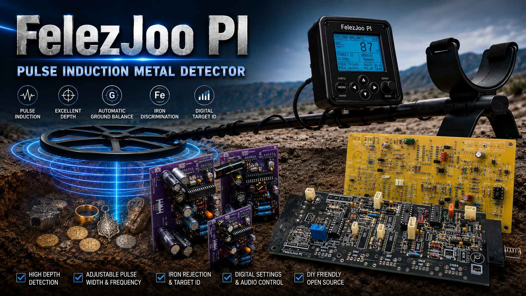
Pulse Induction Metal Detector (FPI)
Version 3.3 — Full build guide, parts list, settings and usage notes
Contents
- Resistors
- Capacitors
- Transistors
- ICs
- Other Parts
- Notes on Selected Parts
- Recommended Coil Specifications
- Assembly and Initial Setup
- Switches: Wiring and Function
- Programming the Microcontroller
- Powering Up for the First Time
- Settings and Menu
- Settings During Normal Operation
- Discrimination and Iron Rejection
- Ground Balancing and Search Technique
- Sensitivity to Gold
- Sensitivity to Ceramics/Pottery and Other Non-Metals
- Hole (Cavity) Detection
- Final Notes
Resistors
| Ref. | Value |
|---|---|
| R1, R17, R21 | 1K |
| R2, R16 | 47 ohm |
| R3 | 10K |
| R4, R14, R20 | 4.7K |
| R5, R18 | 2.2K |
| R6, R15 | 10 ohm |
| R7 | 1.5K |
| R8 | 1.8K |
| R9 | 1M (one megohm) |
| R10 | 100 ohm |
| R11, R12 | 390 ohm — 2W (carbon or metal film, low thermal drift) |
| R13 | 18K |
| R19 | 22K |
- All resistors other than R11 and R12 are 0.25 W (1/4 W) type.
- All resistors should preferably be 1% tolerance or better.
- The accuracy of R7, R8, R10, R14, R19 and R20 is especially important.
- Low thermal drift of R11 and R12 is critical.
Capacitors
| Ref. | Value | Type |
|---|---|---|
| C1 | 10 µF-16V | Electrolytic |
| C2, C3 | 18 pF | Disc |
| C4, C5, C7, C8, C9, C14, C18, C20, C21, C23, C26 | 100 nF (marked “104”) | Small disc (ceramic) |
| C6, C12 | 100 µF-16V (marked “107”) | Tantalum |
| C10 | 5 pF (or 4.7 / 5.6 pF) | Good-quality disc |
| C11 | 2.2 µF-16V (marked “225”) | Good-quality tantalum |
| C13, C17, C25 | 470 µF-16V | Electrolytic |
| C15, C16 | 4700 µF-16V | Electrolytic |
| C19, C22 | 1000 µF-16V | Electrolytic |
| C24 | 2200 µF-25V | Electrolytic |
- Voltage rating is not important for capacitors that are not specified. Using a higher-voltage-rated capacitor is fine, but never use a lower-voltage one.
- Using higher-voltage capacitors, or 100 nF capacitors that are not physically small, may cause fitting problems during assembly.
- The precise value of the 100 nF capacitors is not critical, but they must be ceramic disc (or at minimum multilayer) type. Using MKT/polyester film capacitors for these will make them almost ineffective in the circuit.
- The accuracy of C10, C6 and C12 is important — up to 10% error is acceptable.
- Unlike electrolytic capacitors, tantalum capacitors usually mark the positive lead with a “+” rather than marking the negative lead. If no “+” is visible, a colored stripe next to a lead (tantalum type only) indicates the positive lead; also, on all polarized capacitors, the positive lead is generally longer than the negative one.
- If using a battery with voltage above 24V, C24 should be rated at least 35V.
- Solid or SMD capacitors may be used if they fit properly on the board.
Transistors
| Ref. | Type |
|---|---|
| T1 | BS170 (must be genuine, no counterfeit) |
| T2 | IRF840 — MOSFET (must be genuine, no counterfeit) |
| T3 | BC337 |
ICs
| Ref. | Type |
|---|---|
| U1 | ATmega328P-PU (microcontroller) — 28-pin DIP. Pre-programmed chips are purchasable [limited stock] from the irn-kit.com store. |
| U2 | LF357N (metal-can LF357H, LF157 or LF257 are fine — must not be counterfeit) |
| U3 | L7805CV — 5V regulator, must be genuine |
| U4 | L7812CV — 12V/1.5A regulator, must be genuine, plus a small but strong heatsink |
Other Parts
| Ref. | Description |
|---|---|
| X | 20 MHz crystal (20.000000 / 20.0000 / 20.000) |
| D1, D2 | 1N4148 diode |
| D3 | 1N5819 diode |
| LCD | 16×2 character LCD with backlight — green backlight preferred |
| SP | Two-wire piezo speaker, or headphones |
| BAT | Rechargeable battery, 18–24V, 2A |
| LOOP | Search coil (suggested): spider-wound, ~350 µH, ~1 ohm |
| S | 5 good-quality push buttons mountable on the case (normally open, closed when pressed) |
| PCB | Board suitable for the toner-transfer/iron-on method — fiberglass preferred — 7.3 × 7.9 cm |
- 8-pin and 28-pin (narrow) military-grade IC sockets for IC1 and IC2
- Small, strong heatsinks for the 7812 regulator and, if needed, the MOSFET
- Good-quality shielded coaxial cable without foil shield, for connecting the coil to the board
- Power on/off switch
- Good-quality non-metallic wire and connectors for the coil, header pins, and flat cable for the LCD and ADC connections
- Headphone jack, if headphones are used
- Preferably a non-metallic enclosure and shaft/frame
Notes on Selected Parts
Build cost: The cost of the electronics for this unit (excluding battery, coil, enclosure and shaft) is generally no more than about $20. All parts were chosen to be the best commonly-available options that can be found at several component shops, so no significant cost or effort is imposed on anyone. Those building it for friends should keep this in mind so no one is overcharged.
R11 and R12: Because these resistors heat up gradually during use, their thermal stability directly affects the unit’s stability, especially with ground balance tracking disabled. Any resistor between 360–400 ohms / 2W with lower thermal drift works better than the common 390 ohm 5% type found in most shops. The precise nominal value doesn’t matter much, and a simple ohmmeter check is not a reliable indicator of thermal stability. Testing showed no significant difference in thermal stability between common 390 ohm 1% and 5% resistors; a noticeably better result is only achieved with more precise types such as 0.1% 2W. These precision types usually have 5 color bands and are more thermally stable than ordinary resistors. If such parts aren’t available, the common 5% 390 ohm type works fine without major issues, and 1W types may also be used. In any case, wire-wound or ceramic (brick-style) resistors must not be used for these two positions — only carbon or metal film types.
IC1 (microcontroller): The chosen microcontroller is one of the best in its class, offering more program memory, RAM, processing power, and better ADC performance than lower-tier microcontrollers, giving this design an edge over many other digital designs. However, not every programmer software supports it correctly; the recommended programming method is detailed later. Because firmware updates may be needed periodically, and to allow resetting the on/off usage-count limit, an AVR programmer with USB interface — preferably USBasp type — is required, and users should do their own programming. The “AVR Multi” programmer from ECA (Iran) is a good, inexpensive option, tested to work well with the “AVR Burner eXtreme” software described later. The 28-pin DIP version of this microcontroller is used; the 32-pin SMD version is not compatible with this design.
IC2 (op-amp): This op-amp was selected after testing many common, good-quality op-amps and gave the best results in all tests. It should not be substituted, since the firmware’s signal-processing calculations — especially for discrimination — are based on this specific part; using a different chip may not only fail to work correctly, but could even damage the microcontroller. Unfortunately, many counterfeit LF357 chips exist on the market that will not give correct results, typically showing symptoms like reduced range and incorrect discrimination/iron rejection. Fortunately, a counterfeit chip won’t damage the microcontroller — it simply won’t perform as well as the genuine part.
The metal-can LF357H can be used instead of the plastic LF357N; besides being more stable it is also less likely to be counterfeit. Because this IC’s thermal stability affects the whole unit’s stability, the LF157 or LF257 (military/industrial-grade equivalents of the LF357) can also be used for improved stability, especially in cold weather. In any case this chip must be a genuine part. The MC157 can also be used, though its performance is not quite as good as a genuine LF357.
If using the metal-can version of these ICs, note the different pinout orientation: the round metal package has a tab marking pin 8. Viewed from above, the pin to the left of the tab is pin 1, and pins 2–7 follow around. So separate the four pins nearest the tab from the other four slightly to form a DIP-like shape with pins 1 and 8 identifiable, then insert it into the socket with the tab pointing toward the notch on the socket (toward C10). After fitting, trim any excess lead length so the metal IC sits flush and makes good contact.
MOSFET: T2, the MOSFET, was chosen after testing several common part numbers. The IRF840 has a maximum voltage rating of 500V, which this circuit fully utilizes, giving it a slight edge over the IRF740 (400V rated). Higher power with the IRF840 can be obtained by lowering the coil’s resistance or increasing the pulse width setting. Another number that has performed well and is compatible with the discrimination circuit is the 1000V-rated 10N60, though it showed no significant difference in range. Some IGBT types can also be used. Due to the high voltage present, never touch the coil output or the 2W resistors while the unit is powered — this could cause a dangerous shock.
Under normal conditions the MOSFET only warms up slightly and doesn’t need a heatsink — in fact, its metal tab is prone to picking up noise, and adding a heatsink can increase noise pickup from the surroundings. However, the higher the frequency and especially pulse width settings (particularly both together), the more the MOSFET heats up. For typical field settings this heating is not significant, but if using high frequency or especially high pulse width, a heatsink is recommended both for better MOSFET performance and thermal stability.
If the MOSFET is faulty or installed backwards, the unit may appear to work but with a greatly reduced range.
Regulators: Because the accuracy and stability of the 5V and 12V rails play a central role in this circuit, good-quality regulators must be used. The 7805 doesn’t need a heatsink, but the 7812 must have a small, multi-fin, strong heatsink, since it generates noticeable heat even under normal conditions. This regulator does tolerate heat well, and a small strong heatsink is sufficient; a good-quality regulator won’t suffer voltage drop even when it gets warm. Board space has been allocated for a suitable heatsink, but due to the variety of heatsinks on the market, it’s a good idea to try a few different types to see which fits best at final assembly.
Speaker: The audio output stage is designed to work well with a wide range of speaker types and power levels. If using a small 8-ohm speaker, it should be rated at least 0.2W true power, or the volume should not be set too high, or the speaker could be damaged. That said, since a two-wire piezo speaker performs strongly while drawing less current — giving better stability and lower battery consumption — a two-wire piezo speaker is strongly recommended. Headphones may also be used; if so, include a headphone jack on the case, preferably a volume-adjustable headphone, and if the volume feels too strong you can add a resistor (e.g. ~100 ohm) in series with one headphone wire.
For best results, avoid placing the speaker close to the coil output, to reduce the chance of noise/interference.
Since tone modes 9, 10, 11 and 12 are VCO-based and have no digital volume control, it’s strongly recommended to use the piezo speaker with these modes, adding a series resistor to reduce volume if needed. Using an ordinary speaker under these conditions sharply increases battery consumption during sound output and puts significant strain on the audio stage (R15, T3) and the speaker itself. If using an ordinary speaker with these tone modes, add a resistor (e.g. ~100 ohm) in series with one speaker wire. The same applies to headphones used with tone modes 9–12.
Battery: This circuit works well between roughly 18–24V, with no functional difference across that range. Below 18V performance is compromised, and above 24V the C24 capacitor or the 7812 regulator could be damaged. Since real battery voltage of all rechargeable types drops gradually as they discharge, an 18V nominal battery is the best choice — for sealed lead-acid or dry batteries this could be two 9V batteries in series, or one 12V + one 6V battery in series with matching current rating, or 5 lithium cells in series, which is much lighter and smaller. Lithium-polymer is preferable to plain lithium-ion for being lighter and safer. With lithium cells, a minimum of 5 and maximum of 6 cells in series is required; using 4 cells means the voltage drops below the circuit’s minimum requirement once the charge falls below about 40%, wasting nearly half the usable capacity. Always use the correct automatic charger for whichever battery type is chosen, to charge properly and avoid battery damage later.
Current draw with frequency at 200 and pulse width at 130 measured around 100 mA, and consumption scales directly with these two settings — it can drop to 30 mA with both reduced, or rise to several hundred mA with both increased. Overall, a 2A battery is recommended, giving roughly 10 hours of good operation with default settings — a reasonable compromise. Higher-capacity batteries are fine but only extend runtime without improving stability, since the supply is fully regulated; a bigger battery just adds size, weight and cost, which may outweigh the benefit given how small and cheap the board itself is. However, for continuous use with high frequency/pulse-width settings, using a battery up to 4A is recommended due to the significant increase in consumption. Also, the higher the battery voltage, the hotter the 7812 regulator runs and the more energy is wasted as heat. If battery voltage could exceed 28V, C24 should be rated for 35V.
If battery voltage drops below about 14.3V, since the circuit can no longer operate reliably, a “Low Battery” message is shown and audio response to metal detection is disabled. If the operator continues searching in this state, the unit gives a triple-beep warning every few seconds.
Recommended Coil Specifications
| Coil | Winding |
|---|---|
| 20 cm flat coil | 32 turns of 0.4 mm enamel wire, 19 cm inner diameter (24 turns for a spider-wound version) |
| 30 cm flat coil | 23 turns of 0.5 mm enamel wire, 25 cm inner diameter (20 turns spider-wound) |
| 40 cm flat coil | 19 turns of 0.7 mm enamel wire, 34.5 cm inner diameter (16 turns spider-wound) |
| 60 cm flat coil | 16 turns of 0.7 mm enamel wire, 57 cm inner diameter (13 turns spider-wound) |
| 1×1 m frame | 15 turns of stranded wire, 1 mm² core |
| 1.5×1.5 m frame | 8 turns of stranded wire, 1.5 mm² core |
| 2×2 m frame | 7 turns of stranded wire, 1.5 mm² core |
Enamel wire is preferable for small coils. For large frame coils, stranded/insulated wire is unavoidable, but for the discrimination circuit to work correctly, the stranded wire must have a fairly thick insulation, since this creates spacing between conductor strands that reduces the coil’s internal capacitance — necessary for correct discrimination. This can be judged from the range of the debug 2 (A, B, C) numbers, explained later.
When choosing a coil for a given purpose, note that any coil can generally sense a target down to about 1/20 of its own size well. For example, to detect a 5 cm object, a 1 m frame is about the largest coil usable — larger coils cannot properly detect that small a target, at least not at their center. So using larger coils only extends range for targets larger than 1/20 of the coil’s size.
When comparing same-size coils with different capacitance/resistance characteristics, remember that the Pulse Width (transmit) and Delay (receive) settings mean something different for every coil — so changing coil specs without adjusting these two settings can lead to wrong conclusions about how suitable that coil is. Each coil, with its own capacitance, resistance, and even capacitive behavior, needs its own pulse width and delay tuning to get the best range or stability from it.
Assembly and Initial Setup
The board is designed to be miniature, which both makes enclosure fitting easier and — due to its small size — gives a stronger ground plane and picks up less noise, behaving closer to the theoretical ideal. However, the small size requires more care during assembly, and attention to correct part sizing (especially certain capacitors noted in the parts list) is important. Using fiberglass board is strongly recommended for best results.
After preparing the board via the iron-on/etching method, when drilling, use two drill bit sizes: 0.7 mm and 1 mm. Resistor leads, IC1/IC2 pads, small transistors, small capacitors, the crystal, and the 4148 diodes should all be drilled with the 0.7 mm bit. Use the 1 mm bit for the regulators, MOSFET, large capacitors, 2W resistors, the 5819 diode, and wire connection points. In other words, most holes should be 0.7 mm — skipping this detail can cause serious assembly problems.
Component placement needs no special explanation, except: there are 4 jumpers on the board. The jumper under IC1 (the microcontroller) must be installed before mounting the microcontroller’s socket, preferably using thin insulated wire. The same applies to 2 jumpers near the LCD. However, the jumper between C13 and C15 on the top side of the board should use a thicker wire — for example, a cut-off lead from the 5819 diode or a 2W resistor works well.
Note: the closer components are mounted to the board, the slightly better the final performance will be.
When mounting the 7812 regulator, it’s best to first figure out which heatsink will fit on the board, attach the heatsink firmly to the regulator, and only then mount the assembly onto the board — this makes the job easier.
When installing the regulators and MOSFET, note that the hatched area on the board silkscreen shows the orientation for the metal tab of these parts.
Since the main supply is 12V and some capacitor voltage ratings are chosen based on that, it’s recommended to verify the 12V rail is correct before installing the 16V-rated capacitors — otherwise these capacitors could be damaged.
Never power up a board containing the microcontroller without every single resistor installed! Several resistors, if missing or of the wrong value, can burn out the microcontroller. Take great care that all resistors are correctly placed.
After assembly, do not insert IC1 and IC2 into their sockets yet — first check the voltages marked on the board. Voltage measurements should be taken with a multimeter on DC volts, between the battery negative (the “Shield” point) and the points listed below:
- 12V rail: The jumper between C13/C15, and the LOOP1 point, marked “12V” on the board. Maximum allowed error is 0.2V, i.e. 11.8–12.2V is acceptable. In tests with about 15 different 7812 regulators, all measured between 12.10–12.20V, which is fine. If the error is larger, replace the 7812. If there’s no voltage at all, check the wiring. If the 12V rail measures above 13V, the microcontroller is likely to be damaged!
- 9.5V rail: The common junction of R10 and R14, marked “9.5V” — an important voltage. Its allowed error should track the 12V error proportionally, so the acceptable range is roughly 9.3–9.7V. If the 12V rail is fine but this one isn’t, check R10/R14, and also check C12 for a possible fault.
- 5V rail: Also critical for the microcontroller and LCD; max error 0.1V, so 4.9–5.1V is acceptable. Otherwise, replace the 7805.
If the MOSFET gets hot at this stage, it likely means T1 (BS170) or its wiring is faulty, causing the MOSFET to stay permanently on. Power the unit off immediately in this case, as the MOSFET could be damaged.
LCD wiring follows the usual convention: connect the numbered pads 1–5 and 11–15 on the board to the correspondingly numbered pins on the LCD module itself. If only pin 1 is marked, that marks the start, and pins 2, 3… through 15 follow in order.
Switches: Wiring and Function
The unit uses 5 push buttons for all settings, mounted on the case within the operator’s reach and wired to the board. Wiring is simple: one wire from each button goes to its corresponding point at connector S on the board, and the other wire of each button connects in common to the GND point. So there are 5 signal wires plus one shared 6th (GND) wire connecting the other terminal of all 5 buttons — 6 wires total between the board and the case-mounted buttons.
- OK — enters/exits the menu or confirms a value; placed in the center of the 4 other buttons.
- Left — decreases values in the menu, or decreases sensitivity during search. Placed to the left of OK. (Digit “1” in password mode.)
- Up — moves up between menu items, or toggles debug mode during search. Placed above OK. (Digit “2” in password mode.)
- Right — increases values in the menu, or increases sensitivity during search. Placed to the right of OK. (Digit “3” in password mode.)
- Down — moves down between menu items, or triggers auto ground balance during search. Placed below OK. (Digit “4” in password mode.)
        [Up]
          |
[Left] - [OK] - [Right]
          |
        [Down]
This cross layout is recommended for the case, and since ground balance (Down) is used frequently while searching, it should be as easily reachable as possible for the operator.
Programming the Microcontroller
Programming this microcontroller is not fundamentally different from other AVR-family chips and works with most common programmers. However, since this chip is relatively new, some programmer software either can’t program it or has various issues, particularly with fuse-bit settings. Common tools like the TNM programmer or software like ProgISP, though tested repeatedly, did not give reliable results. It’s strongly recommended to get a USB “AVR Multi” programmer with a ZIF socket, along with the “AVR Burner eXtreme” software, which is a fast, simple, reliable tool for programming this chip — the whole process can take under 1 minute once you know the workflow. If using 64-bit Windows, install the correct USBasp driver, or the software won’t detect the programmer; for simplicity, installing the software on 32-bit Windows is easiest.
Unfortunately, the stock version of AVR Burner eXtreme doesn’t recognize this microcontroller, so a modified version is provided that can program the ATmega328P without issues — but only with a USBasp-type programmer such as the one recommended.
Setup: Connect the programmer to a USB port, then install setup_1.4.2v_avr_burner_extreme. Before first launching the program, go to the install folder (e.g. C:\Program Files\AVR – Burner eXtreme\Data) and replace the two files chips.xml and fuselayout.xml with the versions provided (packaged separately in the zip file). This lets the software correctly recognize the microcontroller.
Open the program, go to the Chip menu, and select ATmega328P. Click the yellow Open button and select the device’s .hex firmware file. If an error occurs at this step, try copying the hex file to the Windows desktop first and opening it from there. Then go to the Fuse Bits/Settings tab to set the fuse bits. There are two possible fuse configurations: one keeps previously stored device settings intact, and one resets internal settings to factory defaults — mostly used to reset the on/off usage-count limit. Note that resetting the fuse bits also resets the EEPROM contents (settings) and the usage-count limit. If the EEPROM ever becomes corrupted, or the usage limit is reached and the device only shows “DEMO!!!” on power-up, reprogramming with the “reset settings” fuse configuration is required. For the very first programming, either configuration works:
| Purpose | Low Fuse | High Fuse | Extended Fuse |
|---|---|---|---|
| Keep stored settings | F7 | D1 | FC |
| Reset settings & usage counter | F7 | D9 | FC |
Then tick the “Write” checkbox next to each of these three fields — don’t tick anything else on this page! With fuse bits set and the hex file already loaded, click the green Write All button to program both the firmware and fuse bits. If the programmer is installed correctly, supported by the software, and the chip is seated correctly, there should be no issues. If the computer doesn’t detect the programmer, you may need the driver disc that came with it, and sometimes unplugging/replugging the USB programmer resolves detection issues. For more detail, consult your specific programmer’s manual.
Any USBasp-type programmer can use the software above to program this chip easily. Given the frequent issues seen with other programmers/software, it’s strongly recommended to get a USBasp-type programmer.
With the “AVR Multi” (ECA, Iran) USBasp-type programmer specifically: the ZIF socket has markings for different pin counts — for this 28-pin chip, align pin 1 of the microcontroller with the position marked “P28” next to the ZIF socket. Programming a blank (first-time) chip differs slightly from subsequent reprograms: for the first programming, the LS jumper on the programmer should be closed; for later reprogramming, leave the LS jumper open and also insert an 8–20 MHz crystal in the marked crystal position next to the ZIF socket, so programming completes correctly and at full speed. Note: newer versions of this programmer have removed the LS jumper entirely, in which case no jumper action is needed.
If using different software for programming, here is the detailed fuse bit table:
| Fuse Bit | Value | Meaning |
|---|---|---|
| CKSEL0 | 1 (Unprogrammed) | External Full Swing Crystal |
| CKSEL1 | 1 (Unprogrammed) | |
| CKSEL2 | 1 (Unprogrammed) | |
| CKSEL3 | 0 (Programmed) | Startup Time: 16K CK/14 CK + 65ms |
| SUT0 | 1 (Unprogrammed) | |
| SUT1 | 1 (Unprogrammed) | |
| CKOUT | 1 (Unprogrammed) | Clock Output disabled |
| CKDIV8 | 1 (Unprogrammed) | Divide Clock by 8 — disabled |
| BOOTRST | 1 (Unprogrammed) | Reset Vector |
| BOOTSZ0 | 0 (Programmed) | Boot Flash Section Size = 2048 words |
| BOOTSZ1 | 0 (Programmed) | |
| EESAVE | 0 (Programmed) | Preserve stored EEPROM settings |
| EESAVE | 1 (Unprogrammed) | Reset settings and usage limit |
| WDTON | 1 (Unprogrammed) | Watchdog Timer disabled |
| SPIEN | 0 (Programmed) | Serial Programming enabled |
| DWEN | 1 (Unprogrammed) | Debug Wire disabled |
| RSTDISBL | 1 (Unprogrammed) | Reset Disable — off |
| BODLEVEL0 | 0 (Programmed) | Brown Out Detection Level = 4.3V |
| BODLEVEL1 | 0 (Programmed) | |
| BODLEVEL2 | 1 (Unprogrammed) |
Note: “0 / Programmed / Enable” means the corresponding checkbox should be ticked; “1 / Unprogrammed / Disable” means it should be left unticked. Any fuse not listed above should be left unchanged.
If the fuse bits aren’t set correctly, the device won’t work properly — symptoms include sluggish response and a very low (often 0) auto-delay reading for the coil. If the crystal/clock fuse bits are correctly set, the unit should boot to the initial ground balance within about 4 seconds. If the BODLEVEL fuse bits (sometimes shown differently in other software) aren’t set correctly, the unit may go into “DEMO!!!” mode after only a few uses and stop working — the only fix is reprogramming with the reset-settings fuse configuration; sometimes this also requires separately erasing the microcontroller’s EEPROM using the programmer software first.
If using the “AVR Burner eXtreme” software, or any software supporting the Low/High/Extended fuse model, none of this bit-by-bit configuration is needed — the 3-byte codes given earlier cover all 11 fuse bits at once, which is simpler and less error-prone.
Powering Up for the First Time
After completing assembly, checking voltages, installing the switches and LCD, and programming the microcontroller, insert IC1 and IC2 into their sockets and power up the unit for the first time. A short beep from the speaker confirms the microcontroller is programmed and the audio circuit is healthy. The one special step for the very first power-up concerns LCD contrast setup, since contrast is controlled digitally: after initial power-up, “Press OK!” appears on the first line, with a counter on the second line that increases while the contrast level cycles simultaneously. As soon as this text becomes visible on the screen, press OK — this saves the initial contrast setting, which can be fine-tuned later from the menu. If nothing appears within a few seconds, wait for the counter to restart, or power-cycle the unit. Important: do not press OK until you can actually see text on the screen — otherwise the unit assumes the current (invisible) contrast setting is acceptable, and you won’t be able to use the display, even if the underlying issue is fixed later, without reprogramming the microcontroller with the reset-settings fuse configuration and repeating first boot. Whenever the microcontroller is reprogrammed with the reset-settings fuses, this initial contrast setup routine repeats.
Settings and Menu
Pressing OK enters the menu. This uniquely designed menu allows increasing/decreasing values with the Left/Right buttons while showing the setting’s name, includes a “wrap-around” behavior, and remembers the last item the operator adjusted — all for maximum convenience and speed. The item currently marked by the arrow indicator is adjustable, and Up/Down move between items. All settings are saved to the microcontroller’s internal memory and persist through power cycles. Settings, in order:
Frequency
Sets the pulse repetition rate (PPS), from 30 to 900 Hz in 1 Hz steps. Lower frequencies give somewhat better ground penetration and less sensitivity to soil mineralization, but reduced sensitivity to smaller targets and slower response; higher frequencies behave oppositely. Battery consumption also increases with frequency. A range of 100–300 is generally recommended for good results across varying conditions. Frequency also offers a way to reduce noise: environmental noise often has its own characteristic frequency, so tuning the detector’s frequency by even a Hz or two can substantially cancel interference in many situations. Because 50 Hz mains noise is common in many locations, avoid odd multiples of 50 Hz; even multiples of 50 Hz have the least interference from mains noise. So 50 Hz is one of the worst choices, while 100 or 200 Hz are among the best.
Pulse Width
Sets the transmit pulse width in microseconds, directly affecting transmitted signal power; range 100–500 µs in 5 µs steps. Along with Frequency, this determines the transmitter’s pulse characteristics — a combination not typically found in comparable digital pulse induction designs. This setting lets you optimize for particular coils, even large ones, and to tune power output relative to coil resistance/capacitance and soil type; getting the best result takes testing and experience. A higher pulse width means higher current/amperage in the coil, but this can be problematic for smaller coils and small targets — very small gold, for example, is not well detected with high pulse width. Conversely, larger targets respond better to higher pulse width; large silver targets in particular can be sensed noticeably stronger with high pulse width. Overall, 150–250 works well across various conditions for this unit. Most existing circuits (often designed for coin detecting) use a fixed pulse width around 100 µs. Values above 350 in this design are mainly included for testing and may only help under specific conditions with certain coils — otherwise these high values can reduce range, hurt stability, or increase sensitivity to ground/mineralization, and battery consumption rises sharply with pulse width. To use the full 500V breakdown voltage of the IRF840 MOSFET, don’t set pulse width below about 150, or the final pulse voltage at the coil drops proportionally. For a MOSFET like the 10N60 (1000V rated, higher Rds), a higher pulse width around 250 is needed to use its full capability. Naturally this also depends on the coil’s capacitance and resistance, so ideally each coil gets its own tuned pulse width.
To protect stressed components when frequency or pulse width are set high, and to cap maximum current draw, a protection system is built in. If the internally calculated battery draw exceeds a threshold after raising frequency or pulse width, a “Power High!” message appears and the unit returns to the menu without saving, refusing to store the setting. In that case, reduce at least one of frequency or pulse width until the unit allows saving and returns to normal search mode. It is possible to use the maximum value of one setting as long as it isn’t combined with too large an increase in the other.
Also, if frequency or pulse width is changed drastically all at once, since it affects the thermal state of the 2W resistors, MOSFET, and to some extent the 7812 regulator, the unit will be unstable after the initial ground balance until these parts reach thermal equilibrium — typically about 1 minute, after which you should re-balance. The same happens with a large decrease in these settings. Initial instability at power-up relates to the same effect, plus the LF357’s own warm-up time. To improve this, use thermally stable 2W resistors, and use a genuine, good-quality MOSFET and 7812 regulator with proper heatsinking.
Delay
This important receiver-side setting determines how long after the end of the transmit pulse (in microseconds) the decaying return signal is sampled for target detection calculations. It starts at 0 and adjusts in 2 µs steps, with its maximum depending on the Integration Width setting. The unit has a unique software feature called “Delay Finder” that can determine the coil’s own starting delay in a fraction of a second during balancing. The manual Delay setting in the menu represents additional delay, in microseconds, added on top of the auto-delay baseline (equivalent to 0). So any value set here means: auto-delay plus that extra delay after the end of the transmit pulse. This matters because small targets like small gold need a shorter delay for good detection, but at short delay the detector also becomes more sensitive to ground effects, mineral particles, and some rocks/pottery. So depending on soil and target, it’s often beneficial to manually increase delay. A manual delay of +20 to +60 works well in most conditions. However, at higher delay, sensitivity to smaller targets (especially small gold) decreases — so for smaller coils intended for small targets, a high delay setting isn’t ideal. Delay tuning is thus experience-based, depending on the operator’s goal, coil, and local soil. For smaller coils, a delay around +25 is recommended; for larger coils, a proportionally higher delay helps reduce ground/mineral effects and can even improve detection strength/range for larger targets. A higher manual delay reduces ground sensitivity but slightly reduces range too — this can be compensated by raising sensitivity, which restores range while keeping reduced ground/mineral/small-target sensitivity — one of the benefits of the delay control.
If you need a delay higher than the current menu allows, first reduce the Integration Width setting to allow more delay range.
W.Integ (Integration Width)
One of the more unique, professional-grade settings compared to other designs, this determines how long (in microseconds) after the Delay point the return-signal integration — which is the basis of metal detection — continues. It starts at 10 µs, adjustable in 2 µs steps, with its max depending on the Delay setting. Some analog designs call this “RX Width.” The precise integration window starts at auto-delay + manual delay and lasts for the value set here. For example: if auto-delay reports 20, manual delay is set to +40, and W.Integ is 44, integration is calculated over the window from 60 to 104 µs after the transmit pulse ends. This setting, along with Delay, affects detection of different metals, sensitivity to certain minerals, and to some degree noise susceptibility. Setting it too low reduces range; increasing it may slightly increase apparent range but also increases susceptibility to ground effects. Some pulse induction circuits dedicated to small-gold detection use a value around 20 µs here, but since that hurts range for other metals (especially larger targets), for general-purpose detecting or larger targets a higher value is better. This setting requires experience to tune well — if unfamiliar with its exact effect, use the default (44).
If you need an integration window wider than the menu currently allows, first reduce Delay to allow a wider integration range.
Ground (Automatic Ground Tracking)
Similar to Self Adjusting Threshold (SAT) in advanced pulse-induction detectors, but with improvements, this behaves more like the “Tracking” feature in Minelab GPX-series machines, and is also similar to the “Auto” setting in Lorenz detectors. Important during long search sessions, this feature is a major differentiator from many simpler detector designs, making extended searching over a large area easier, since it eliminates constant need for re-balancing. If conditions don’t change abruptly and the unit is left running for hours, unlike most designs, this detector will maintain its maximum range/sensitivity setting throughout. It also continuously adapts to changing weather conditions that affect circuit stability, always delivering the expected range at the sensitivity level you’ve set. Adjustable range: 0/OFF to 20. OFF disables tracking, giving a “fixed” balance requiring frequent manual re-balancing but with slightly better range/sensitivity. Other values enable tracking — lower numbers mean faster tracking, higher numbers mean slower, more gradual tracking. The best value depends on the operator’s sweep speed, coil size, and soil type, and is best found by experience.
For example, in highly variable/poor soil, lower values are better despite somewhat reduced range, requiring faster sweep speed to detect targets reliably. For better, more uniform ground, higher Ground values are more suitable and increase range. If conditions change abruptly during searching, pressing the balance button may be necessary. If extra scrutiny is needed to confirm a weak target, it’s advisable to switch this to OFF at the final moment of pinpointing to confirm the presence of that faint target. Also, with tracking disabled the unit responds faster with a warning beep when encountering a hole or going out of balance. Note that the ground-tracking system mainly benefits performance at high sensitivity settings; at low sensitivity, it’s better to turn Ground off, or a significant range loss could result.
Also note: with this feature enabled, air-testing a target is somewhat different — since the unit gradually and automatically adapts to its environment, slowly approaching a target from a distance is not a valid test method, and the range may appear to fluctuate. Special provisions exist for this, but the exact peak-detection boundary can’t be accurately measured this way, so range measured this way won’t be accurate. The correct way to air-test range with Ground enabled is to sweep the target past the coil at a reasonable speed, similar to real search conditions — as if sweeping the coil around a suspected target’s location in real use. The Ground setting is designed for, and matches, this kind of realistic testing. For a more precise maximum-range test, place the target near the coil’s center, then slowly move it away until the audio response cuts out, and measure that distance as max range. With Ground off, the test method doesn’t matter.
Speed
Similar to the “Motion” setting in Minelab GPX-series detectors, this determines the detector’s response speed to a target. It behaves inversely to the “Filter” setting on Lorenz detectors — i.e., low values here are equivalent to higher filter values on Lorenz machines. This capability, absent in typical detector designs, gives very good stability and noise rejection, greatly reducing spurious beeps during searching. Adjustable 1–10. Lower values mean slower response but maximum stability and noise rejection; higher values mean faster response with less stability and more noise susceptibility. For example, setting 10 gives near-instant target response, while setting 1 may take a few seconds to announce detection. The right value depends on sweep speed, target goals, and coil size; for maximum stability, use a lower speed setting. Naturally, lower settings require slower sweep speed, or weaker targets may be missed. Lower settings can also automatically help filter out small targets/particles. As a rule of thumb, smaller coils work better with higher speed values, and larger coils with lower speed values, for a better and more stable result. This system is “smart” — if a target’s response is strong enough, this setting is overridden and the target is announced at maximum speed. With lower speed settings, thanks to improved stability and quieter background, sensitivity can often be raised a bit further, improving range.
Although Speed is largely independent from Frequency, if using Speed = 10 and still needing faster response, raising Frequency further increases detection speed. But at Speed settings of 1 or lower, Frequency no longer significantly affects response speed.
This setting similarly affects response speed to holes or loss of balance — the higher the value, the faster the warning beep triggers when a cavity is encountered.
Iron Reject
Modeled on Minelab GPX-series systems, using complex iron-identification formulas from Minelab’s approach. Unlike Minelab/Lorenz pulse systems, where iron rejection only works with DD (double-D) coils and effectively doesn’t work with large mono coils, this design’s iron rejection works with any mono coil size. Adjustable 0/OFF to 30. OFF disables iron rejection; other values enable it and set the rejection strength. The higher the value, the stronger the rejection, but eventually other (non-ferrous) targets start getting rejected too. When enabled and a target is identified as iron, the audio output cuts off, but the graph, meter, and the discrimination number/”FE” label on the LCD still indicate the detection. Working with and calibrating this setting depends heavily on build quality, coil, and search environment, and is covered in detail in another section.
BackLight
Possibly a first for such a design, this digitally controls LCD backlight brightness. Adjustable 0/OFF to 10. OFF means backlight off, 10 means maximum brightness. Some LCD modules have differently wired backlight circuits requiring a jumper change on the back of the LCD to work correctly — if that jumper can’t be changed, use a different LCD brand. The backlight circuit is designed so that even at maximum brightness, battery consumption doesn’t increase noticeably, so there’s no need for concern on that front.
Contrast
Similar to the previous setting but controls how dark the text appears on the LCD. Adjustable 0–30. Lower numbers mean darker text, higher numbers mean lighter text. Since LCD panels vary, and viewing angle depends on LCD placement on the case, the shaft design, and how the unit is held, the operator can tune this for the clearest readability for their own use.
Volume
Controls audio output strength; OFF means fully muted, 10 means maximum volume. Note: if using tone modes 9, 10, 11 or 12, this setting no longer affects the detection-response volume — only OFF will fully mute sound in those modes. Given this unit’s strong audio output, it’s recommended not to use very high volume, especially with an ordinary speaker, since this reduces stability and increases battery consumption. The audio system includes a “rising tone” effect for tone modes 1–8, where the sound gets slightly stronger as a target gets closer to the coil. For this effect to work well, it’s recommended to keep volume relatively low; above volume level 7, the rising-tone effect becomes less noticeable. This rising-tone effect for approaching targets also works better with an ordinary speaker than with a piezo speaker.
With Volume set to OFF, all sound is disabled; if BackLight is not off, all detection responses and warning beeps instead appear as the LCD backlight flashing — more suitable for nighttime use. In that mode, if Iron Reject is enabled and a target is identified as iron, instead of muting audio, the backlight flashing simply stops.
Tone
Selects the audio tone mode for target response. Adjustable 1–12.
- Modes 1, 2, 3 — single-tone: treble, mid, or bass respectively.
- Modes 4, 5, 6 — two-tone combinations.
- Mode 7 — three-tone combination.
- Mode 8 — a “sliding” tone that shifts from treble (weak signal) toward bass as the target signal strengthens, becoming its deepest at maximum signal strength.
- Modes 9, 10, 11, 12 — VCO (voltage-controlled oscillator) modes with continuously variable pitch. Volume settings have no effect in these 4 modes; a piezo speaker is recommended for these, as noted earlier. In mode 9, weak signals sound high-pitched, becoming lower as signal strengthens or the target gets closer. Mode 10 is the reverse — starts low, rises in pitch as signal strengthens, closer to the sound style of some professional detectors. These modes help pinpoint the target’s center more precisely.
- Mode 11 — pitch tied to the discrimination number: before discrimination locks in, the tone is very high-pitched; once discrimination activates, pitch corresponds to the discrimination number (lower discrimination number → higher pitch, higher number → lower pitch).
- Mode 12 — the reverse of mode 11: very low pitch before discrimination is determined, then lower discrimination numbers give a deeper tone and higher discrimination numbers give a higher tone — closer to professional detectors’ audio discrimination style.
Multi-tone combinations help distinguish real targets from false signals/random noise, and help better identify the target’s center. While tone choice is a matter of taste, mode 10 is recommended. The audio response style of some detectors, such as Lorenz, resembles tone mode 10. In multi-tone modes 4, 5, 6, the speed of pitch transitions naturally depends on the detector’s operating frequency, but in the three single-tone modes and modes 8–12, there’s no relationship between operating frequency and the tone.
Password
For personalizing device access and preventing unauthorized use — and possibly a first for such a design — a password option is included. Since there’s no full keyboard, a simple 1–10 digit password using digits 1–4 is used. When the unit is in password-entry mode, Left = digit 1, Up = digit 2, Right = digit 3, Down = digit 4; entered digits are shown on screen. After entering the password, press OK for the unit to evaluate it. It’s recommended to label digits 1–4 next to the direction buttons on the case for convenience.
This menu item behaves a bit differently: pressing Left or Right while the menu cursor is on this item opens a different screen. If a password is already set, “Old Password” is shown first, and the operator must enter the current password. If entered incorrectly, “Wrong Password” is shown and the unit returns to the menu without allowing a change. If entered correctly, “New Password” is shown for entering the new code. The password can be 1–10 digits, chosen freely, and OK confirms entry. Then “Confirm Password” appears, requiring re-entry of the new password for confirmation. If the confirmation doesn’t match, like a wrong-password case, the unit returns to the main menu without changing the password. If the confirmation matches, “Password Changed” is shown, the new password is saved, and the unit returns to the main menu. If a password is set (non-empty), the menu shows “ON” next to the Password item; if empty, it shows “OFF,” meaning no password is active.
If a password is set, next power-up shows a “?” prompt requesting the password before anything else. Enter it and press OK — if correct, the unit boots normally; if not, it re-prompts and won’t proceed until the correct password is entered.
To remove the password: go to the Password menu item, enter the old password, then at the “new password” prompt simply press OK without entering any digits (an empty password), and repeat this at the confirmation step. The unit will then have no password, and “OFF” will show for this setting.
Choose a password carefully — secure enough, but memorable. If forgotten, the only recovery is reprogramming the microcontroller with the reset-settings fuse configuration.
About
Shows device and designer information only, with no other function. With the menu cursor on this item, press Left or Right to display the device name, firmware version, then designer info; after a few seconds the unit returns to the main menu screen.
- Sensitivity is not adjusted from within the menu — see the “Sensitivity” section under normal operation below.
- After finishing any menu adjustments (one or more settings), press OK to exit the menu and save all changes. If Frequency, Pulse Width, Delay, or W.Integ (settings affecting ground balance) were changed, the unit automatically re-runs the balance routine once after exiting the menu.
On common questions like “is this detector sensitive to mineralization/pottery?”, “how sensitive is it to gold?”, “how does it work with a large coil?”, or “what coil suits this circuit?” — these questions are essentially meaningless for this particular design. Given the full range of adjustable settings described, there is essentially no factor typical of pulse induction detectors that can’t be tuned digitally on this unit. Replicating this entire feature set in an analog circuit would require at least 10 potentiometers and even more ICs, and still wouldn’t match the digital system’s performance. With this design, a simple set of digital adjustments effectively creates a “new” detector each time, with different characteristics. Certain settings drastically cut sensitivity to mineralization, others boost small-gold sensitivity; maximum sensitivity to large metal objects, or better ground penetration, can each be dialed in by adjusting settings. So this design is a fully flexible, adaptable replacement for thousands of purpose-built detector designs, allowing a good result to be tuned for the operator’s needs and conditions.
On dealing with noise: Frequency, Speed, and Ground settings all affect noise. With a bit of testing in the actual search environment — just nudging these settings up or down — noise can often be dramatically reduced, to the point that even the highest sensitivity settings become usable. Since noise character varies by environment, if spurious beeps are noticed at high sensitivity, a bit of patience testing these settings can find a good noise-rejection configuration to continue searching with. It’s best to test noise effects first with Speed at maximum and sensitivity set high, observing extra beeps and especially fluctuation in the sense meter or debug-1 reading across different settings. When adjusting settings — especially frequency — the debug-1 reading shows less fluctuation, that setting has less noise. Confirm that setting, then reduce Speed to further filter noise, and finally raise sensitivity to the highest level with no spurious beeps. This achieves maximum sensitivity combined with stability. Ground tracking also plays a role in noise handling — it’s often better enabled in noisy conditions.
Settings During Normal Operation (Search Mode)
Auto Ground Balance
Pressing Down during normal search runs the auto-balance routine (this also happens automatically at power-up). This first finds the coil’s auto-delay value, shown on screen in microseconds, then performs the final balance to establish silence/quiet threshold. Note: during the auto-delay stage, a reading around 20 indicates the coil and its cable are close to ideal; the higher above 20 the reading, the greater the coil/cable’s capacitance and the lower its quality — this reading tends to run higher for ordinary coils. A slightly-above-20 auto-delay can help stability, but if it exceeds about 30, chances of detecting small gold drop significantly, and discrimination/iron rejection performance may suffer too.
If, after pressing balance, the coil is disconnected, shorted, or otherwise incompatible with the circuit’s minimum requirements, a “Coil Error!” message appears and the unit halts. To continue, fix the coil/cable issue and press balance again. Since balancing also runs automatically at power-up, a faulty coil prevents the unit from working at all, protecting the circuit from damage and avoiding wasted battery. A “Coil Error!” can also result from the coil being too close to large metal objects, or internal circuit faults, including the LF357 or its surrounding components, T1 (BS170), the MOSFET, or incorrect microcontroller fuse programming.
Naturally, if the coil is near metal during balancing, a higher delay reading — or even a coil error — may result, so ensure the coil is away from metal when balancing.
If the coil is swapped while the unit is powered on, re-balance by pressing Down. It’s recommended, though, to power off (or at least be in the menu screen) when swapping coils.
Sensitivity
Controls receiver sensitivity for target detection, adjusted with Left/Right during search — Left decreases, Right increases, with the level shown on screen. Adjustable 1–20. Lower values mean less sensitivity/range, higher values mean more. The maximum setting may not be practical in every situation, since it would require zero noise and perfectly ideal conditions, which is never achievable — but the better the build and environment, the higher a sensitivity level can be usefully applied, for greater range. The typical practical range for pulse detectors is usually near the upper portion of the sensitivity scale, combined with good stability. The maximum level is included partly for testing and partly to demonstrate that this unit’s range is not artificially capped. Note: with changes to key parameters like Frequency, Pulse Width, Delay, and Integration Width, the practical meaning of “sensitivity” shifts, so it may be necessary to re-tune sensitivity after adjusting those, for best performance.
Important: aside from the very top setting, the range difference between adjacent sensitivity levels is no more than about 2–3%. So even at sensitivity level 1, you still get roughly 60% of maximum range, and level 10 gets you to about 90%. Also, since this circuit’s internal receiver gain is considerably higher than most standard pulse-induction designs, in many environments — depending on ground conditions — the very top few sensitivity levels may simply be unusable, with even small changes in coil height above ground causing extra beeping or a negative meter reading. Given that even a weak, possibly-false target with a sense meter reading of 10 (which might not even reach the discrimination threshold) is detectable at sensitivity level 18, there’s no need to insist on the very highest sensitivity levels. So, for wide-area searching aiming for confirmed, discriminated targets, sensitivity 10–16 is generally recommended; use the higher levels mainly for searching a specific marked spot where even a very weak signal matters. Note: at low sensitivity settings, it’s better to turn Ground off, or an additional range penalty results — the ground-tracking system mainly benefits high sensitivity settings.
Also, increasing/decreasing sensitivity only affects overall (all-metal) range and has no effect on discriminated range.
Debug
Pressing Up during search replaces the normal top-line summary with diagnostic info. First press (Debug 1): shows an integral symbol and the live calculated overall integration value of the return signal on the top LCD line. A second press (Debug 2) shows information from the 3 discrimination channels, labeled A, B, C. A third press returns to the normal settings summary. In either debug mode, if a target is detected, discrimination info is not shown; only the audio cutting out (if Iron Reject is active and iron is detected) still occurs. So debug modes should not be active if you want to see live discrimination data while detecting.
These debug displays have no effect on detection quality — they’re for testing/diagnostics. For example, the operator can gauge noise level via fluctuation in the Debug-1 integral reading; better sensitivity depends on this number being more stable with less fluctuation. This lets you evaluate different build choices, shielding, or settings by monitoring this number’s stability, since ultimately maximum range depends on maximizing noise rejection. Similarly, examining the Debug-2 channel readings (A, B, C) helps verify correct operation of the discrimination system and the unit overall, covered in another section.
The Debug-1 value’s magnitude depends on Delay and Integration Width settings, so there’s no fixed “correct” range for it — what matters is stability/low fluctuation, indicating good noise rejection. In Debug-2, the three channel numbers aren’t tied to these settings, only slightly influenced by Frequency and Pulse Width.
LCD Information During Search
During search, as long as no target (or only a weak one) is detected, the first line shows a summary of key settings, so you always know the active configuration. Due to limited display space, abbreviations are used: S = Sensitivity, D = Delay, F = Frequency, P = Pulse Width, with the value shown to the right of each letter.
When a target’s signal is strong enough for the discrimination data to become valid, the first line changes entirely: “ID” appears at the left, followed by the target’s discrimination number (0–99). If Iron Reject is enabled, the target’s ferrous/non-ferrous status is shown as “FE” or “NON-FE,” with the iron meter reading to the right. If Iron Reject is disabled, instead the word “FERRO” is shown along with a fixed-scale iron-meter reading. The top line reverts to the settings summary shortly after target signal is lost. Details on this are covered in the discrimination section.
Pressing Up during search instead shows the live integral reading, or the A/B/C discrimination channel data, as described above.
The bottom-right of the second line shows battery voltage, accurate to about 0.1V (larger error depends on the accuracy of R10/R20 and the 5V rail). If battery voltage readout seems inaccurate, check these two resistors and the jumper under the microcontroller. From the displayed battery voltage, you can gauge charge state depending on battery type — e.g. for 6-cell lithium-ion/polymer packs in series, ~24V means fully charged and ~19V means fully depleted. Below about 19V, circuit performance becomes unpredictable and stability/range drop. Below 14.3V, “Battery Low” is shown on the bottom-left and audio response for detection is disabled. When powering off, “Power Off” is shown on the bottom-left, and after a special tone, the unit shuts down.
In normal search mode, the left side of the second line shows a bar-graph representing detection strength, active simultaneously with the audio response. This unit also has a 3-digit numeric “sense meter” to the right of the bar graph, indicating target-detection strength numerically. The stronger the signal (bigger target, or closer to the coil), the higher this number. With experience on specific targets and a given coil, the operator can use this meter to estimate probable depth or even the chance of a false signal. For example, if the meter changes a lot as the coil is raised/lowered over a spot, that suggests a shallow target; if it changes little as the coil moves away from the ground, that suggests greater depth. Similarly, a wide detection area with a low meter reading may indicate a large, deep target; a narrow, fast-changing detection area suggests a small, shallow target. If the meter doesn’t peak clearly at the center of a wide detection zone, that can suggest a false signal or scattered mineral particles. Another benefit of the sense meter is more precise pinpointing: especially when the target is somewhat distant from the coil, a target directly under the coil’s center is usually sensed most strongly, giving the meter’s highest reading there; but for small, shallow targets, the strongest response might actually occur near the coil’s edge rather than center. So this digital meter helps pinpoint the target center more precisely and better estimate target size.
If the unit encounters a hole, or the coil moves too far from the ground, and sometimes right after a target signal is lost, the sense meter may show negative numbers — indicating momentary loss of balance, or a possible cavity. In this case, the unit periodically emits a warning beep. If Ground tracking is enabled, balance is usually automatically restored shortly, and the negative meter reading disappears. Note the sense-meter scale relates to most settings, but Sensitivity has no effect on the meter reading for a given target — so the same target gives the same meter reading regardless of sensitivity level.
In normal search with no target or hole detected, two symbols — “_” and “!” — alternate on the bottom-left of line 2. Alternation between these while sweeping is normal, especially at high sensitivity. But if the coil is held still and these symbols still alternate, that indicates noise. If the coil moves away from the ground or approaches a cavity condition, “!” is shown steadily before a negative meter appears.
Discrimination and Iron Rejection
The discrimination and iron-rejection system uses 3 channels separate from the detection channel, designed using engineering principles from Minelab and Lorenz detectors. The single most important point for most users: discrimination/iron rejection has absolutely no effect on the unit’s detection sensitivity or maximum range. Unlike many designs with discrimination, this design’s discrimination does not cost any range, and enabling/disabling iron rejection has no impact on overall detection range.
When a target is detected close enough to the coil for discrimination calculations to be valid, and the unit isn’t in debug mode, a 2-digit number from 0–99 (the Target ID, or discrimination number) appears next to “ID:” on the first line. This ID is based on conductivity, roughly comparable to Lorenz-brand machines — refer to the “Target Classification” section and table in a Lorenz Deepmax X3/X5/Z1 manual to interpret these numbers, though ID numbers on this unit tend to read somewhat higher than the equivalent Lorenz scale. The idea that a discrimination number reveals metal composition is entirely mistaken — target size, shape, and even permeability/thickness affect this number more than composition. Generally, the larger and thicker a non-ferrous target, the higher the ID number. So there is no single fixed ID number for “gold” — but large, solid gold targets typically show an ID above 70. Iron typically shows ID numbers in the 30–60 range, though this range can overlap with many other targets, so the iron-rejection result is far more reliable than the ID number alone for judging ferrous/non-ferrous status. Very small or thin targets, like foil, typically show ID numbers below 20. Since pulse systems (unlike VLF systems) aren’t affected by certain sine-wave-related target effects, even very large iron targets typically don’t exceed an ID around 70 (depending on the specific build), making iron rejection more reliable for large targets on this design than on typical VLF machines.
If Iron Reject is enabled in the menu, based on a separate calculation formula running alongside the ID number, when iron is identified, audio cuts off and “FE” (ferrous) is appended after the ID number. If the target is identified as non-ferrous, audio continues and “NON-FE” is shown instead. In both cases, a 2-digit positive/negative meter is also shown, indicating — based on the Iron Reject strength setting — how firmly the target falls into the ferrous or non-ferrous zone. For ferrous (FE) targets, a negative number is shown; the more negative, the more firmly ferrous. For non-ferrous (NON-FE), a positive number with a “+” prefix is shown; the higher, the more firmly non-ferrous. Unlike the ID number (which is fairly consistent for a given target across conditions), this iron meter depends entirely on the Iron Reject setting. Testing several ferrous and non-ferrous targets and observing this meter lets you fine-tune the Iron Reject level more precisely in the menu. Occasionally the iron meter may show a negative value even while the unit still reports “NON-FE” and keeps audio on — full ferrous identification depends on additional conditions in the firmware beyond just the meter value, so the most reliable indicator is the FE/NON-FE label paired with the audio response; the iron meter is mainly for extra scrutiny and confidence. At the start of a strong, discriminated iron detection, a brief beep is normal and expected — after that, once the calculations settle on “ferrous,” audio cuts off fully and “FE” is displayed. If Iron Reject is set to OFF, there’s no FE/NON-FE labeling or audio muting for iron — instead, “FERRO” is shown after the ID number, followed by a 2-digit unsigned number on a fixed scale (dependent on circuit/coil characteristics) indicating how iron-like the target is; the higher this FERRO number, the closer to iron.
Discrimination range is roughly 80% of the unit’s overall detection range for a given target (varying by target type) — the unit itself determines whether the signal is strong enough for valid discrimination/iron-rejection calculations. In the outer ~20% of range where the signal is too weak for discrimination, the unit operates in “All Metal” mode, showing no discrimination/iron info — just the graph, meter, and a generic detection beep.
Calibrating iron rejection: An important step, dependent on your specific circuit build, coil, and search environment. First, make sure the coil is far from any metal, including large objects, so results aren’t skewed. Then, using iron tools like pliers, a large screwdriver, a key, a heavy iron chain, or a piece of rebar/I-beam, test different Iron Reject level settings. With a correctly tuned rejection level, most iron targets should show an iron meter (FE) reading between -3 and -15, and most non-ferrous targets should show +3 to +15. For example, if testing an iron target gives a meter reading beyond -15, the rejection level should be lowered. A simpler way to find a good rejection level: first set Iron Reject to OFF and check the FERRO number for an iron target. Then the suitable rejection level is approximately: (100 − FERRO) ÷ 3 + 2. For example, if FERRO reads 61 for iron, the suitable rejection level is about 15. If the rejection level is set more than about 2 steps above the ideal, non-ferrous targets gradually start getting rejected too — so choose carefully. Since different coils can behave somewhat differently, remember the correct rejection level per coil, and re-calibrate after swapping coils. For best confidence, also perform this test in the actual search environment with the coil held at normal search height above the ground, so ground conditions are factored in. Done this way, you can expect over 80% accuracy in rejecting genuine iron trash. Besides the automatic rejection, the ID number itself can help confirm.
Another way to judge iron: set Iron Reject to OFF and estimate ferrous status from the FERRO number alone. For example, if FERRO reads around 40 for non-ferrous and 60 for ferrous targets, values above 50 suggest iron and below 50 suggest non-ferrous. You should also cross-check the ID number, since iron targets’ ID is typically no lower than about 30 and no higher than about 70. The example values given are dependent on the specific unit/coil and should be evaluated before actual searching.
Unfortunately, some targets that aren’t purely ferrous can’t be reliably rejected — for example, tin-plated cans (tin coating) are essentially impossible to reliably reject, though old, rusted cans buried in soil have a decent chance of being identified and rejected. Various stainless steel items may or may not be rejectable, depending on iron content. That said, most fully-ferrous trash — nails, chains, farm-tool fragments, etc. — is reliably identified and rejected by the system.
Correct technique matters a lot when working with discrimination/iron rejection. For example, sweeping the coil too fast over a target can cause discrimination errors. So once a target is detected and its data suggests it’s within discrimination range, hold the coil steady over the strongest-signal point (highest meter reading) for a few seconds, letting the unit refine its calculations to a stable ID and more confident ferrous/non-ferrous call. Since coil angle/orientation relative to the target slightly affects discrimination results, readings from different angles or the target’s edges may vary somewhat — this can actually help evaluate the target better, but the reading directly over the target’s center is always the most meaningful. Also, for accurate discrimination, don’t change the coil’s height above ground during this process, since the unit bases its calculations on the last known coil-to-ground distance before target detection — so maintain consistent coil height over the target too. On the other hand, the system is designed to work at long range as much as possible; if a target suddenly gets very close to or touches the coil, the discrimination channels can overload, giving no valid ID or ferrous data at all.
Correct operation of iron rejection, in particular, also depends on the unit itself being in good condition. On the board, having a genuine LF357 (or the other approved part numbers) is key, along with healthy C10, C11 and MOSFET. On the coil side, it’s important that the coil’s auto-delay reads around 20; a coil with a delay above about 30 won’t give good discrimination results. So follow the recommended coil specs, and always use a proper coil cable/connector. For initial home testing, choose a location genuinely far from any metal objects, or the iron rejection system won’t function correctly. While most conditions can be handled well by adjusting the rejection level, outdoors — without interfering metal — you should re-tune the rejection level again for best results. Failing to follow the above may result in iron rejection failing entirely, or conversely rejecting many non-ferrous targets too. Another sign of correct discrimination operation is the ID number itself: very small/thin non-ferrous targets should show an ID under 20, and large/thick aluminum-type targets should show an ID around 80. Most medium/large coins should show an ID in the 30–60 range — for example, a large white 500-toman coin (Iranian coin) reads about 40. Large, old buried targets typically read above 70, even 80, in which case there’s a better chance of the target being valuable. Note: an ID of 99 usually indicates an error/glitch. If ID readings are consistently very high or very low for all targets, the LF357, coil, or MOSFET is likely at fault.
If, for any reason, iron rejection doesn’t give acceptable results at any menu level, you’ll have to set Iron Reject to OFF to disable it. Even then, the ID number can still help estimate target type, and the FERRO meter may help somewhat too, though it becomes less useful if it always shows very high or very low values in that mode. It’s strongly recommended to fix whatever circuit or coil issue is causing unreliable discrimination/iron identification.
Discrimination and Iron Reject calibration depend slightly on Frequency and Pulse Width, but the resulting shift in ideal rejection level is at most about one step. Delay, W.Integ, Ground, and Speed have no effect at all on discrimination or iron rejection, since those only affect the detection channel. So it’s best to first decide on frequency and pulse width for your search conditions, then test/tune iron rejection.
For deeper verification of the discrimination system’s correct operation, a second debug mode is provided. Pressing Up twice during search shows 3 numbers next to A, B, C labels, containing the 3-channel discrimination data. On the reference unit tested, with no metal near the coil, these should read roughly A≈300, B≈700, C≈800. Exact numbers don’t matter and shift slightly with frequency/pulse width changes, but the general magnitude and ratio between them should resemble these figures — a large deviation indicates a serious circuit fault, likely the LF357, coil, or MOSFET. For instance, A should be between roughly 200–400, ideally 230–350, for the iron-rejection system to work well on any of the menu’s levels. B should be roughly twice A, give or take. C should be larger than B, by roughly 100 units or so. So these approximate readings, combined with an auto-delay around 20, confirm the whole unit — LF357, MOSFET and coil — is working correctly, without needing an oscilloscope to check waveforms.
When a target is being detected, these 3 numbers will naturally read lower. Similarly, placing the coil on an indoor floor or near a wall containing metal building materials will reduce these numbers, especially A. So before placing the coil near any surface, be sure there’s no metal behind it.
Naturally, noise also affects discrimination quality — the better the unit’s normal detection stability, the more accurate and stable the discrimination/iron-rejection performance. In noisy environments, discrimination at longer range may be less accurate; a telltale sign is the ID number constantly changing. The more stable the ID number, the more trustworthy the discrimination — and especially the iron rejection. So if the ID number fluctuates by more than about 3 units repeatedly, don’t fully trust the iron rejection result in that case, and don’t rely on intermittent beeping (a sign the unit is “unsure” about ferrous status) either.
Also note: reducing sensitivity has no effect at all on discrimination range — sensitivity only affects the detection channel. So at sensitivity levels around 10 or below, discrimination tends to activate almost simultaneously with detection, meaning discrimination range can equal overall detection range at that setting.
Another point: discrimination range relative to overall range differs by target. Larger targets with a higher ID number discriminate sooner, and at a weaker meter reading. So for valuable buried-treasure-type targets with high ID numbers, discrimination range could be as much as 90% of overall range for that target! Conversely, for very small or thin targets with a low ID number, discrimination activates later and discrimination range is proportionally lower. So if the sense meter shows a strong signal but discrimination hasn’t kicked in yet (unusually), you can reasonably guess the target isn’t likely to be anything valuable. Overall, more definitive than the ~80% iron-rejection accuracy is the fact that targets with an ID below 20 are essentially never going to be valuable finds.
An important caveat about trusting the iron-rejection system: in specific situations with multiple different metal targets positioned together in the ground, there’s always a chance the unit mistakenly calls something ferrous. So how much you trust the system, accepting the roughly 20% predicted error rate for iron rejection, versus the risk of missing a valuable target, is up to the operator. This design deliberately erred slightly on the cautious/strict side for iron rejection, so even with Iron Reject enabled, there’s always a brief beep at the initial moment of ferrous detection — giving the operator a chance to check the on-screen discrimination data and decide for themselves.
Ground Balancing and Search Technique
While proper balancing technique for any detector depends heavily on the environment, coil, and search method — with operator experience being the biggest factor — here is the recommended balancing approach for this unit.
With Ground tracking enabled (automatic terrain/environment adaptation active), it’s best to hold the coil at the same height above ground you intend to search at, press the balance button, wait a few seconds, then begin searching.
With Ground set to OFF (disabled) — since there’s no automatic ground tracking — balancing to the terrain is more of an experience-based, trial process. On ground that shows some response when the coil is brought close, it’s best (with Ground off) to hold the coil slightly closer to the ground than your normal search height when balancing, then raise it slightly and continue searching.
Also, whenever balancing any detector, always balance in a spot you’re confident has no metal nearby! Otherwise the balance is skewed by a hidden target, and moving the coil over the ground afterward will show a negative meter and knock the unit out of balance. This is actually a sign that metal is likely present where you balanced — move away a bit, re-balance, and continue.
An important detail for searching with any detector is proper coil height above ground. Based on research and testing, the minimum suitable coil-to-ground distance is roughly 3 cm per 30 cm of coil size. For example: a 30 cm coil needs about 3 cm clearance; a 60 cm coil needs about 10 cm; a 1×1 m coil needs about 25 cm; and a 2 m coil needs about 45 cm clearance from the ground, to minimize ground effects on detection and get better stability and discrimination. This matters even more if the unit loses balance from small coil movements. Naturally, keeping this clearance won’t cost you range — and in fact may even slightly increase effective range due to better stability. Conversely, holding the coil too close to the ground causes instability, noise, ground/mineral sensitivity, and reduced discrimination accuracy, while excessive clearance beyond what’s needed clearly reduces range.
Also, for scanning ground with any detector, it’s crucial that coil height and angle relative to the ground stay as consistent as possible — don’t let it wobble. So sweep the coil so it stays parallel to the ground, maintaining a consistent height as much as possible. Achieving maximum sensitivity/range with acceptable stability depends heavily on this sweep technique. Naturally, larger coils require slower sweeping and minimal raising/lowering. The overall shaft/frame design of the detector matters a lot here — if the shaft’s dimensions and angles don’t suit the coil size and the operator’s build/height, maintaining consistent height and coil-to-ground parallelism becomes much harder. So it’s strongly recommended to base the shaft design on well-established, reputable detector designs.
To reduce sensitivity to ground moisture and mineralization, several specific points matter. Besides proper coil clearance (discussed above), settings also help. The most important is Delay — generally, the higher it is, the lower the ground sensitivity. A Delay of at least +20 or more is recommended for ground searching, though too high a delay eventually reduces range, especially for smaller targets. Similarly, Pulse Width should be set to the minimum value that still gives close to maximum range for large targets — any extra beyond that only adds ground sensitivity and unnecessary battery drain. Lower frequencies also give somewhat lower ground sensitivity and better penetration, though 100–200 Hz still gives very good results. For highly variable/inconsistent soil, if Ground is enabled, lower tracking values are better — this costs a little range but improves stability. Conversely, for more uniform/favorable ground, a higher Ground value can achieve more range without instability. Also, if you can’t maintain consistent coil-to-ground height well, lowering the Speed setting helps prevent spurious beeps from small height fluctuations. Finally, after applying all these points, sensitivity should still be reduced enough that no instability is observed while searching.
If, while searching, bringing the coil close to the ground itself triggers a discriminated detection, that indicates unfavorable ground conditions — especially for wet or mineralized soil, the higher the ID number for the “ground signal,” the more conductive (and less favorable for detecting) the soil is. In such cases, it’s better to hold the coil at a greater distance from the ground, apply the settings adjustments noted above, and then search. If possible, choosing a time when the ground is drier gives a stronger, better result. Also, in areas with a lot of mineral particles, larger coils generally perform better.
Searching inside a pit or hole requires special technique and more experience. Before digging a hole for a target, evaluate the detection/discrimination data carefully first, then decide whether to dig. When searching inside an existing pit, use a coil smaller than the pit, balance on the pit wall first, then continue searching inside. Alternatively, use a coil considerably larger than the pit itself. Otherwise, because a pit behaves somewhat like a cavity (the opposite effect of metal), depending on soil type, range may drop or the unit could go out of balance. Also, if the initial target signal was weak, this negative pit-effect is more pronounced, and there’s also a risk that digging disturbs/moves the target enough to weaken or eliminate its detection “halo,” so it may not be detectable anymore after a preliminary dig! So for weak targets, extra care and evaluation before digging is important. Based on experience, this is one specific reason a target can seem to disappear after preliminary digging, and treasure hunters sometimes — without realizing this cause — attribute it to superstition about the treasure “moving,” when in fact this technical effect explains it.
Sensitivity to Gold
A common question among treasure hunters: “how sensitive is this detector to gold?” — some claim a given circuit “has no sensitivity to gold” or, conversely, “is extremely sensitive to gold.” Strictly speaking, such statements aren’t scientifically/technically accurate. First, small gold — with low, short-duration conductivity response — behaves very differently from large gold. Large gold detects essentially the same as other metals, with no meaningful difference. Small gold, however, naturally gives a weaker signal and needs specific settings and a suitable coil for good detection. A key issue in early testing is that, given gold’s high price, people often test with pieces that — regardless of composition — simply wouldn’t be well detected by any pulse induction detector. For example, fine-link chain, which is porous/permeable, won’t be reliably sensed by a pulse detector whether it’s gold or not. But solid pieces like coins, bracelets, and rings are detected well by pulse detectors. So keep this in mind when testing gold response.
For detecting small gold specifically, a few things matter. First, coil type matters — a coil intended for small gold should have a low delay reading (“fast coil”) to properly sense small gold’s short time-constant response. Flat or spider-wound coil types suit this purpose, and naturally a small coil size (e.g. 20 or 30 cm) should be used for small targets — a large coil simply won’t detect a small target well, which is expected. Beyond the coil, various settings help small-gold detection: high frequency, pulse width around 150 or even lower, low manual delay, and high Speed setting all help sense small targets like small gold better. So if the goal is such a target, apply these settings, and expect performance quite different from large-target detection with large coils.
Two more subtle points about gold hunting: first, since gold has always been a valuable metal, by the same logic its likelihood of being present in various locations is lower than more common, less valuable metals! Though this runs counter to a treasure hunter’s hopes, it’s simply reality. Second, due to gold’s physical nature, it becomes less “ionized” relative to many other buried metals, so the halo effect that can boost detection strength over time is weaker for gold — this is one of the very properties that makes gold valuable. For most old buried metals, thanks to this halo effect, expected field range can be 100%, even up to 2x, greater than air-test range — but this can’t be expected for gold, which might at best be sensed slightly stronger than air-test values. That said, if — as often happens — another metal happens to be near the gold, the halo effect from that other metal can boost the combined detection, and greater-than-normal range can then be expected.
Sensitivity to Pottery/Ceramics and Certain Non-Metals
An important point every operator of any detector should understand: fundamentally, all metal detectors — regardless of underlying technology — detect metal based on its electrical conductivity. So whatever techniques or design details go into different detectors, none can escape this basic principle — otherwise they might fail to detect certain metals, or suffer a large range loss for others! So marketing claims that a given detector is “not sensitive to pottery/ceramics” and similar are, generally speaking, simply not accurate. Some types of pottery are detected by every detector, and some types by none. This can be verified even with the most expensive, reputable detectors on the market with a few tests.
Given the above, the reason wet, mineral-rich soil is detected comes down to the same principle: it’s electrically conductive and can pass current. This and how to handle it were covered earlier. Similarly, some (not all) types of pottery — especially in moist soil — can give a detection response comparable to metal. This depends on the materials used to make that particular pottery, and moist soil amplifies its conductivity effect. Some strongly-responding pottery types may show an ID number between 30 and 50, which can help you guess at pottery — though this ID range also overlaps with many metal targets, so it’s not conclusive proof the target is pottery. Recognizing a pottery signal takes considerable experience. For weakly-responding pottery types, lowering frequency and pulse width, and raising delay, can reduce or eliminate the signal. Also, where pottery fragments are scattered, unlike a real metal target, the signal often lacks a clear peak/center — meaning even though there’s a broad, extended detection zone, the meter may not increase steadily toward a center point but fluctuates instead. This can indicate scattered particles, including broken pottery.
Also, in some environments, certain rocks contain metallic particles that naturally get detected. Some of these rocks give a fairly strong signal. Fortunately, if these particles are magnetic (i.e. an “iron rock” target), the iron rejection system can identify and reject them well.
One useful way to spot false signals during a search of an area is watching for repeated discrimination patterns. For example, if a target is detected, dug, and found to be a false signal, remember its ID number and iron-meter reading; if a nearby target shows the same discrimination signature, you can reasonably conclude it’s likely another false signal of the same kind, saving unnecessary digging.
Hole (Cavity) Detection
Although a detector’s main job is metal detection, and it can’t identify a hole/cavity as clearly as metal, under certain conditions this detector can be used to sense holes too! For that reason, the sense meter on this unit is signed, and just as positive numbers indicate metal detection, negative numbers can indicate the presence of a hole/cavity. The technical reason for the difference between a hole and metal is again conductivity: metal is far more conductive than soil, while a hole has the opposite effect. So under the right conditions and settings, depending on soil type, holes can be sensed too.
For hole-hunting (unlike metal detecting) you want the unit to sense the ground itself more strongly, so differences in the returned signal for cavity areas become more evident. So using a lower delay and higher frequency/pulse width works better for sensing holes. Also, since you’re evaluating instantaneous meter changes, it’s better to disable Ground tracking. Ground tracking, while helpful for metal detection at high sensitivity, doesn’t help hole detection. Under these conditions, if bringing the coil close to the ground triggers a detection response (meaning the unit senses the ground itself well), there’s a good chance of successfully sensing a hole. Otherwise, that ground probably won’t yield hole detection and is better suited to metal detecting than cavity detecting.
Given the above, and watching for the negative meter number to increase at a specific spot, you can suspect a possible cavity there. The unit signals this with warning beeps, and if Ground tracking is disabled, the beep rate increases.
In some cases, soil differences in an area relative to its surroundings can create a cavity-like effect for the detector — for example, areas with looser/softer soil, or old pits/wells that were later filled in, usually show a weak cavity-like signature.
If a negative (cavity) meter reading appears just before a metal detection, it usually suggests the metal target may be sitting inside a larger cavity! In this case, the unit signals the cavity first, then detects the metal.
Final Notes
As you can tell, the hex firmware file for this detector is fairly large, comprising thousands of lines of code — matching the extensive feature set. So minor changes/fixes are likely across most areas over time, and new features will keep being added. The pace and progress of this project depends on those willing to build it, share results, and offer constructive feedback and suggestions to help refine the design. Ultimately, the biggest beneficiaries are the builders themselves. My request to everyone: unlike past common practice, please avoid modifying the circuit itself; if you believe something is genuinely wrong, contact me privately so I can review it — this is one reason the schematic isn’t published openly. In any case, the circuit design is straightforward, and everything has been calculated and tested to the best of my ability to reach the best possible result, leaving no room for major circuit-level mistakes. The same applies to the board layout — some unauthorized modifications there could also hurt performance. For anyone who feels this design isn’t good and, as has happened before, wants to disrupt the project’s progress out of jealousy, rivalry, competition, or personal interest — I’ll say plainly: this is now my own personal project. If you have something to say, go build and pursue your own project and design as you see fit. Otherwise, no non-technical interference will be accepted from my side.
Download Files
This content is available to logged-in users only.
هذا المحتوى متاح فقط للمستخدمين المسجلين.
Ce contenu est réservé aux membres connectés.
🔑 Login 📝 RegisterLog in or create a free account to access downloads and exclusive content.
This content is available to logged-in users only.
هذا المحتوى متاح فقط للمستخدمين المسجلين.
Ce contenu est réservé aux membres connectés.
🔑 Login 📝 RegisterLog in or create a free account to access downloads and exclusive content.


