
Capacitors work without problems, but sometimes they encounter power failures or malfunctions. If the problem is noise, then there is a simple solution, just add more capacitors. But if that doesn’t work out, what went wrong?
The root of the problem is that we take capacitors for granted as ideal devices, but they are not. These unexpected results are due to internal resistance, or equivalent series resistance (ESR). Capacitors have limited internal resistance due to the materials of their internal construction. There is also the equivalent inductance (ESL).
Different types of capacitors have different ESR ranges. For example, electrolytic capacitors generally have higher ESR than ceramic capacitors. In many applications today, obtaining the equivalent resistance of a capacitor has also become one of the important design factors. In this post we will use a NE555 timer and a transistor to measure the ESR of the capacitor.
Capacitor ESR measurement
ESR measurement looks very simple. The resistance can be calculated by applying a constant current and measuring the voltage drop of the device.
What if we apply a constant current to the capacitor? The voltage increases linearly and the final value is set to the input voltage. Such a value is useless for calculating the ESR.
At this time we have to think about a sentence we heard in school-“Capacitors block DC and AC”
after simplification. We can understand capacitors as short circuits at high frequencies, and the capacitive part is cut off from the circuit , and the rest the voltage is applied to the internal resistor.
The advantage of this method is that if we know the internal resistance of the signal source, we don’t need to know how much the current value is, because the ESR and the internal resistance of the signal source form a voltage divider. Its resistance value ratio and voltage ratio can be obtained by knowing three parameters. Know the remaining parameter.
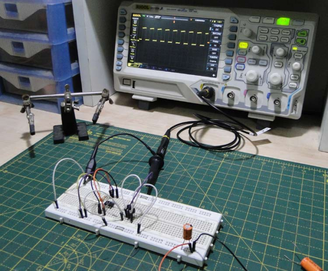
We use an oscilloscope to measure the waveforms on the input and capacitance.
Required Components
- Oscilloscope
- NE555 timer with high frequency is recommended.
- 100kΩ potentiometer-used to adjust frequency
- 1nF capacitor
- 10uF ceramic capacitor- decoupling
- BC548 NPN transistor
- BC558 PNP transistor
- 560Ω resistor
- 47Ω output resistance-you can choose this resistor in range of 10Ω to 100Ω
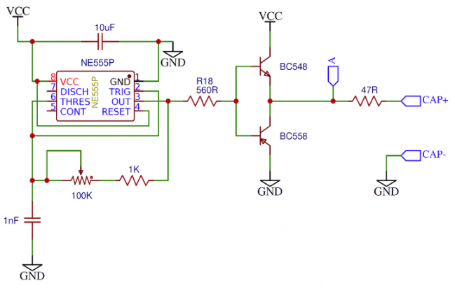
The ESR measurement circuit can be divided into two parts, the 555 timer and the output stage.
1- The NE555 timer is a conventional astable Multi-vibrator oscillator , may generate hundreds of kHz square wave. At this frequency, almost all capacitors are equivalent to short circuits. A 100kΩ potentiometer allows us to get the lowest possible voltage on the capacitor.
2- Power stage: We can connect the capacitor directly to the NE555 timer, but then we should know the precise output impedance.
To solve this problem, we use a push-pull output stage and a series resistor here. This resistor is used to provide the output impedance. The following picture is the ESR measurement circuit.
Calculation of capacitor ESR
From the voltage divider equation we can get the following equation:
ESR = (VCAP * ROUTPUT) / (VOUTPUT – VCAP)
where ESR is the internal resistance of the capacitor and VCAP is the signal voltage between the capacitors (measured at CAP + point) ), ROUTPUT is the output resistance (47Ω) of the power stage, and VOUTPUT is the output signal voltage measured at point A.


