
Building the search DD coil for Induction Balance metal detectors
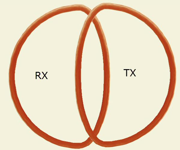
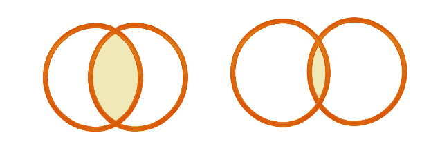
The name of this Coil DD comes from the similarity between its two parts (the receiver and sender coils) and each coil takes the form of the capital letter D, meaning that it consists of two coils (double) similar to the letter D. The layout of the components can be seen in the following figure.

For the accuracy of model, it is never necessary to obtain a duplicate letters DD. The shape of the two coils can be oval, round and even rectangular, but it is only better that both coils are the same in shape. Induction Balance is achieved in this design by determining the size of the interference between the interfering area between the two coils. It’s easy to think that in this part sandwiched between the receiving coil and the transmission coil, the EMF in the TX coil is directed in the opposite direction to the RX coil, and a fine tuning of the device can result in a virtually zero EMF value. To reduce the impact of soil and external interference, the receiving coil must be protected with an insulating screen, and some manufacturers of this coil also protect the transmission coil, but this is unnecessary when using a low operating frequency. It is not always necessary to set the receive circuit at the electrical resonance (it is sufficient to use a capacitor of the same capacitance in the receiving circuit as it is in the transmission circuit). The value of capacitors can be calculated and installed directly on the coil as in the search coil for Quasar and Quasar ARM metal detectors.
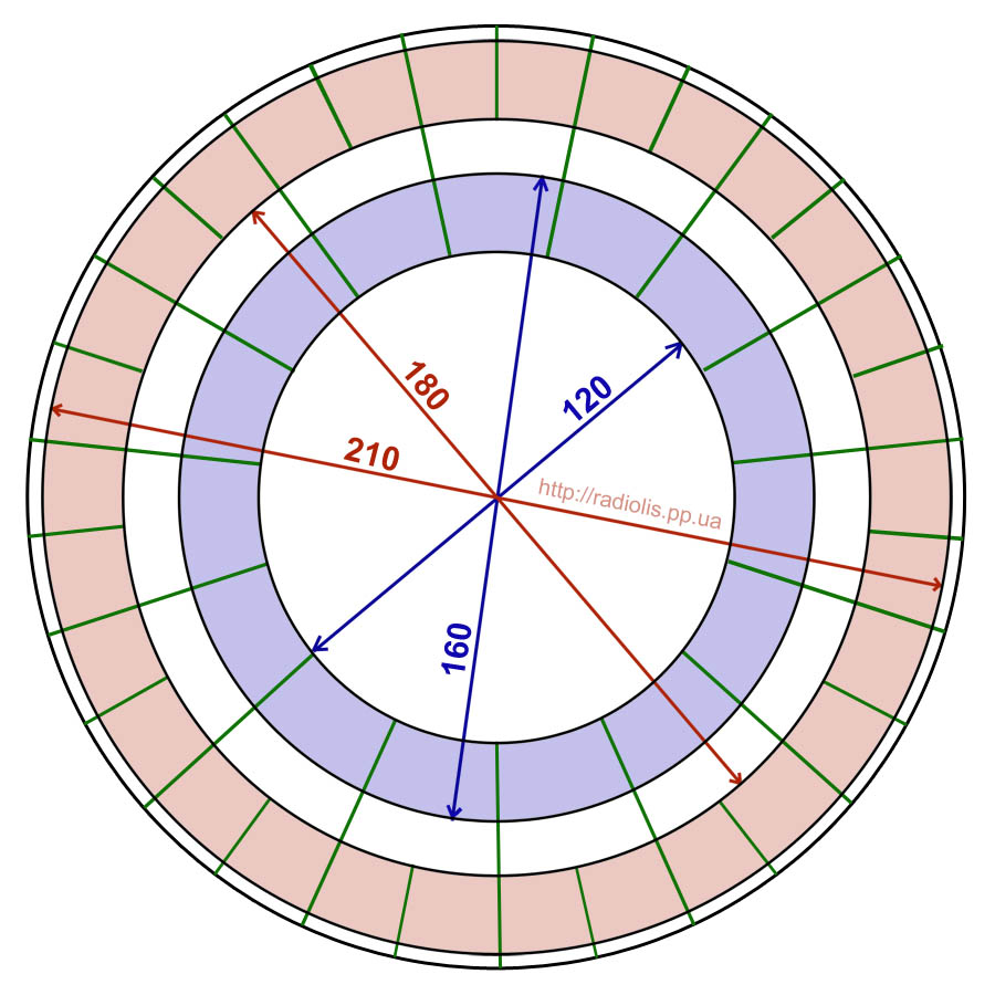
After obtaining the properties of the coil that we want to manufacture (the diameter of the RX and TX coils, the diameter of the copper wires, the inductance value, the number of turns … etc.) it is possible to start building the coil. Calculate the properties of coils from the site: her
The windings are wrapped in a pre-prepared pattern with the required diameter. In this type of coil, it is recommended to use the maximum diameter of the copper wire by 0.7 mm to avoid high resistance value, which affects the resonance frequency of the device.
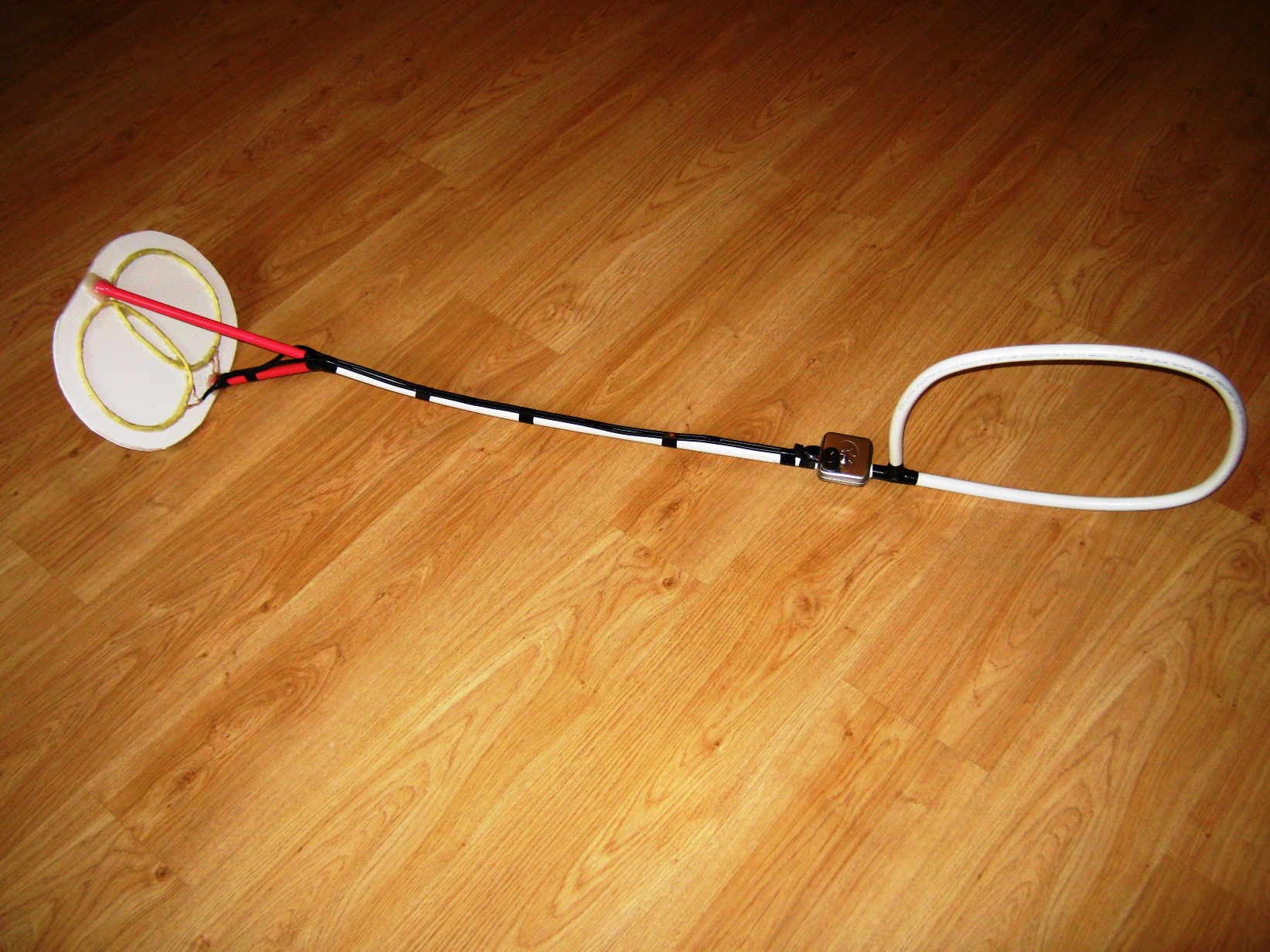
The optimum diameter of the two coils usually ranges between 15-16 cm, and circular object models should be used so that the two coils are wrapped around it. You can use a clean wooden surface and need a hammer and nails in a circle pre-drawn with the required diameter.
The windings are wrapped in a pre-prepared pattern with the required diameter. In this type of coil, it is recommended to use the maximum diameter of the copper wire by 0.7 mm to avoid high resistance value, which affects the resonance frequency of the device.
The optimum diameter of the two coils usually ranges between 15-16 cm, and circular object models should be used so that the two coils are wrapped around it. You can use a clean wooden surface and need a hammer and nails in a circle pre-drawn with the required diameter.
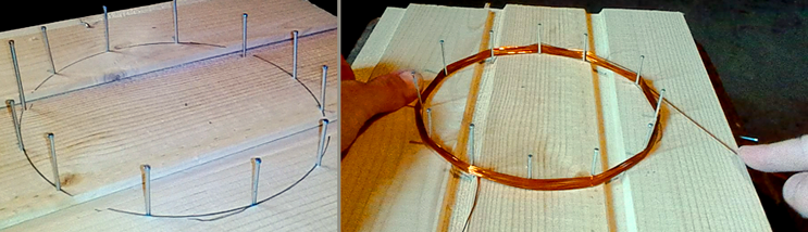 The inner diameter in the photo is 15.5 cm with 12 points marked with nails. With regard to the copper wire is wrapped about 50 turns in this coil and can be obtained from old electric motors or electrical transformers.
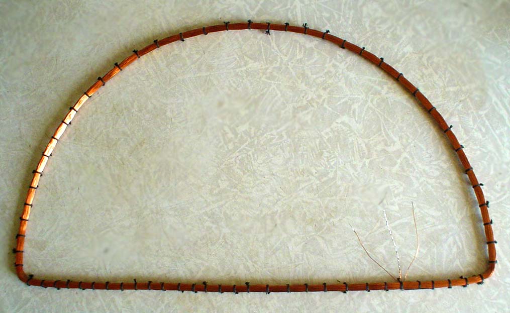
When winding the coil, carefully remove it from the wood board and wrap it with a paper tape to keep the coils in place. The TX and RX coils are made in the same way, taking into account the number of turns in relation to the two coils (some devices work on a DD coil consisting of two TX and RX coils with an uneven number of turns). After that we strip the ends of the copper wire with a knife at the ends in preparation for welding it with the cable.
To obtain the DD shape, we transfer the two coils to obtain the required geometry, so the insulation paper must be wrapped on both coils completely. Next, we need to settle the TX and RX coils slightly as they overlap each other in a small area. They are often made as shown in the figure below.
 The electronic PCB of the metal detector should be located about 1 meter from the search coil. It is not recommended to use regular wires to connect the coil to the device, and it was necessary to use a shielded wire used in the microphone and some other applications.
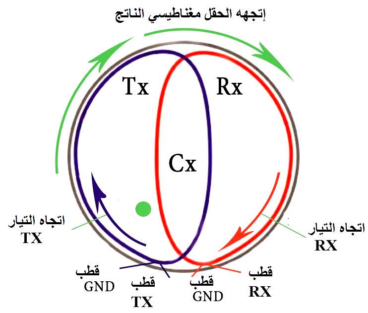
The following figure shows the correct method for installing the final Coil DD and current direction in coils TX and RX which must be opposite to obtain a zero EMF region CX. The final coil contains four terminals that are attached to the device’s PCB at the points that previously marked.
The CX should be modified before the two coils are permanently attached to the base. Therefore the device should be adjusted to the highest possible sensitivity. And then we need to move the two coils to increase and decrease the CX region, and this depends on each device. However, it is recommended to place the two coils so that their overlapping is as tight as possible.
Finally the Coil DD can be installed on a well insulated carrier and start working on the device.


Hi,
What frequency should be applied to this TX coil?