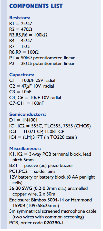
This design is arguably the simplest IB (induction balance) metal detector that could be built from off the shelf components. The IB method of metal detection has a good depth of penetration and discriminates well between ferrous and non-ferrous metals.
Metal detectors are available commercially but their price tag is often prohibitive to young- sters and those just starting out with the trea- sure hunting hobby. This article proposes a metal detector that is fun to build at a very low investment. Carefully built and aligned, it will clearly pick up a tiny 15mm dia. brass coin at 70mm in air, or a 25mm coin at 120mm. It will not fail to pick these up vaguely at up to one quarter greater distance. The ability to locate coins buried in the soil are, of course, dependent on soil conditions, dry sand being the most favourable, and clay, the worst, ‘medium’ between the treasure and the search head.
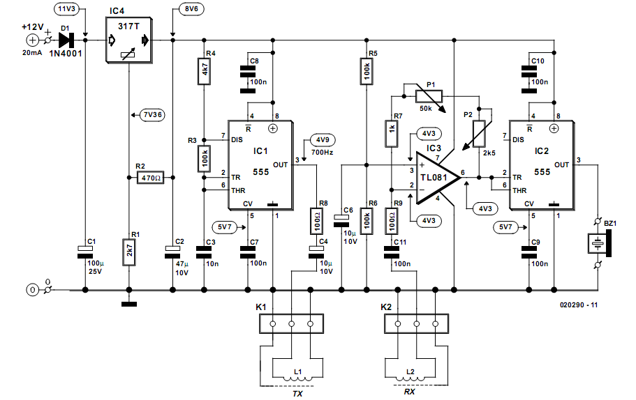
The electronics
The electronics you’ll need to build for this project is relatively simple and based on common or garden components only — some of which you may already have available in the junkbox or your regular compo- nent supply. The electronics (Fig- ure1) consists of a pulse transmitter and an associated receiver, with one–way traffic using two coils as a medium. The transmitter is built around IC1. The CMOS (low-power) 555 gen- erates a square wave output signal with a duty cycle of nearly 50% and a frequency of about 700Hz. With the 555 in astable mode the output fre- quency is determined by compo- nents R4, R3 and C3. The output pulse is applied to TX (transmitter) coil L1 via series network R8-C4, with the electrolytic capacitor block- ing the passage of DC through the coil, and the resistor protecting the output stage inside the 555. The pulse edges generated by the 555 will excite the coil and cause damped oscillation bursts at the self- resonance frequency of about 10kHz. The receiver section (IC2) is pre- ceded by a simple yet effective preamplifier stage based on opamp IC3, which amplifies the signal received from the RX (receiver) coil, L2 via C11-R9. The gain of the opamp is adjustable using P1 (coarse) and P2 (fine). The second CMOS 555 in the circuit, IC2, is configured to act as a true threshold detector, its output (pin3) going High as soon as the sig- nal level at the input (pin2) drops below 1/3 of the supply voltage (or about 2.9volts). Likewise the output drops low again as soon as the volt- age at the THR input (pin6) exceeds 2/3 of the supply voltage or about 7.4volts). So, a 700-Hz signal will just start to sound from the piezo buzzer if the carefully adjusted threshold is exceeded. This adjust- ment is extremely critical and the ‘crux’ of the circuit.
Coupled coils
The TX and RX coils are critically coupled so that the presence of metal will disturb their magnetic coupling and with it the carefully adjusted ‘quieting’ of the threshold detector. Both coils have the same size and have a partial overlap. This enables the RX coil to pick up a pos- itive as well as a negative (inverted) portion of the magnetic field gener- ated by the TX coil. Because at care- ful balance of the coils the positive and negative signals cancel out each other, in theory the RX coil will sup- ply zero output signal. This we will call a ‘null’. However, because of (for- tunate) practical restrictions, a very small residual signal will always be generated. Once the delicate bal- ance between the fields is disturbed by the presence of a metal object (which will absorb magnetic field energy) the RX coil will start to sup- ply a higher output signal, causing the electrical threshold set up on IC2 to be exceeded, and the buzzer to start sounding. In practice, the detector adjustment is optimal with the passive piezo buzzer producing a soft crackling sound in the absence of metal. At this setting, the sound level increases considerably when a metal object is detected. The adjustment of the ‘null’ posi- tion of the coils is critical and will be described further on. The circuit is powered by a 12-V battery or a battery pack consisting of 8 penlight (AA) batteries or recharge- able cells. The use of an external bat- tery pack carried on the shoulder will reduce the overall weight of the meta detector considerably. It also enables a fresh pack to be substituted quickly. The on-board voltage regulator, IC4, is configured with R1 and R2 to supply an out- put voltage of 8.6V. Current consumption from the battery pack will be of the order of 20mA depending mostly on the buzzer activ- ity, of course.
Construction — the PCB
Populating the printed circuit board shown in Figure2 should not present problems because the board is spacious and only leaded components are used. Beginners should take strict guidance from the parts list and the component overlay printed on the board. As you can see from the photographs in Figures3 and 4, the potentiometer shafts run through the board. This is done to allow knobs to be fitted once the shafts have been cut to a length which is determined by the enclosure. As we are dealing a with a pretty sensitive piece of equipment, we recommend using a metal enclosure. This also allows the potentiometer cases to be grounded via the retaining nuts and washers.
Construction — search coil assembly
The constructing of the coils takes you into the much dreaded realms of ‘mechanical construction’ although some would argue for ‘tin- kering away on a Sunday afternoon’. What- ever, it will present a welcome change from handling your soldering iron and those com- ponents you know so well. Below is a search head description (as suggested by the author) which we have no reason to question for veracity! Because a pic- ture tells more than a thousand words, refer- ence is made to Figure5. Both coils are identical. If you can get it, use 33SWG (0.26mm) enamelled copper wire, winding 100turns in a clockwise direction on a circular 15cm diameter former. The wire diameter is not critical — anything between 0.2mm and 0.3mm will do just fine. The coil is then temporarily held together with stubs of insulating tape passed under it and pressed together over the top. It may be jumble- wound. A second coil is wound in the same way. Each coil is then tightly bound by wind- ing insulating tape around its entire circum- ference.
Next, add a Faraday shield to each coil. This is accomplished with some long, thin strips of aluminium- or tinfoil. First scrape the enamel off the base of each coil’s end wire. Solder a 100 mm length of bare wire to the base, and twist this around the coil, over the insulating tape. This provides electrical contact for the Faraday shield. Beginning at the base of this lead, the foil is wound around the circumference of the coil, so that no insulating tape is still visible under the foil — but the foil should not complete a full 360 degrees. Leave a small gap – say 10 mm – so that the foil does not meet after having done most of the round (if you go all the way, you’ll create short-circuited winding that will introduce a formidable amount of unwanted attenuation). Do this with both coils. Attach each of the coils to quality balanced (or ‘symmetrical’) screened microphone cable, with the Faraday shields being soldered to the screens of the cables. Do not use “stereo” screened (microphone) cable — this may cause interference between the coils. The cable you need has two twisted signal wires inside a common screening braid. Each coil is now again tightly bound with insulating tape around its entire circumference. Last of all, wind strips of absorbent cloth around each coil (dishwashing cloth should suit), using a little all-purpose glue to keep them in place. Later, when resin is poured over the coils, this cloth meshes the coils into the resin. Gently bend the completed coils until each one is reasonably flat and circular, with each end wire facing away from you, and to the right of the beginning wire. Now bend them further, until they form lopsided ovals — like capital D’s, as shown in the diagram. The backs of the D’s are positioned so that they overlap each other slightly on the search head — this is the critical part of the operation, which will be performed after the printed circuit board has been completed.


Again, the coils need to be screened (with tin- or aluminium foil) to make sure they only respond to their own magnetic field, eliminating the risk of signal breakthrough (caused by even the smallest degree of capacitive coupling). Defective or inadequate screening will result in fast pulse edges from IC2 arriving directly at the input of IC3. These stray pulses will make it impossible to find a ‘null’ in the search coil adjustment (see below).
Adjustment
As you may have gathered, construction of the search head is not yet finished. At this point, however, some construction aspects start to interact with the adjustment of the circuit. Confused? Read on.
A completed and properly working printed circuit board is needed before we can ‘pot’ the coils. They are potted with plastic resin in a hard non-metallic base-plate. Any baseplate of suitable size will do, on condition that it is rigid. The author’s prototype was potted on a suitably cut piece of masonite, with ‘walls’ made of 5 mm wood dowel glued around its edges. These walls should be ‘resin-tight’. Do not use any metal in the search head. Also, cover a 4 cm segment of coil with Blu-Tack (Pres-Stik) so that it remains unpotted, and may be bent for final adjustment if required. First place the coils on top of one another — ensuring that they are correctly orientated, with each end wire facing away from you, and to the right of the beginning wire. Turn the gain pots fully counter clockwise (minimum gain) to reduce the amplification to minimum. Attach a 12 V battery pack, and switch on. Now slowly move the coils apart until the buzzer is quiet. This is where the voltages in the Rx coil ‘null’. Increase the gain somewhat and tweak the coil positions again. Repeat this adjustment several times, each time increasing the gain. The higher the gain can be set when still finding a null, the more sensitive the detector will be. Always move the coils from fully meshed to fully apart, not the other way around. If you adjust at the ‘wrong side’, the signal level on the coils will first drop when a metal object is detected, pass through the null, and then increase again to a level where the buzzer starts to sound. That’s ok in principle, but the detector will be very insensitive. Take your time to positively identify the optimum coil positions. If necessary use a wooden jig for easier mechanical adjustment and comparison of results. Once you’ve found the precise point where the coils need to be set, take a marker pen, and mark for holes around both coils. These holes are used to pass cable-ties through, to hold the coils tightly to the base-plate. Also use a cabletie to hold the microphone cables to the baseplate. Use some Blu-tack (or Pres-stik) to tightly seal the holes underneath the plate before pouring the resin — plastic resin can be very ‘runny’, and sticks faster than many glues. Carefully bend the coils at the centre of the plate until you reach the exact balance at which there is neither silence nor screaming in the buzzer or headphones, but a crackle. A little drift should not matter at this point. You might also wish to attach a swiveljoint to the search head at this point, which will be attached later to the metal detector’s shaft. One-inch (or larger) PVC kitchen drainage conduit may be used for the shaft. Now you are ready to mix and pour the resin.


Use the correct amount of catalyst, so that there is not too much heat and shrinkage in the resin. Pour the resin over the cloth which surrounds the coils, so as to soak it, and keep on pouring at least until the entire bottom of the plate is covered with resin. The circuit may no longer function correctly at this point until the resin has hardened, so make no more adjustments at this stage, but switch the circuit off.
When the resin has set hard, keep the search head away from all metal, and away from computer equipment, which can cause serious interference, and switch on. Adjust potentiometer P2 (fine-tune) to their mid-points. Then adjust P1 (tune) until the metal detector is just at the point where a crackle is heard, between silence and a scream. Use the tune and fine-tune knobs for any further tuning. Move a coin over the search head, and the piezo sounder should ‘scream’.
In actual use
You’ll soon find that the adjustment of the metal detector will be affected by the mineralisation of the ground you are searching, as well as temperature and voltage variations — so readjustments to P1 and P2 are inevitable. One trade-off for the extreme simplicity of this design is some drift. While it is not excessive, re-tuning will be necessary on a fairly regular basis.
At the centre of the search head, the circuit’s rejection of iron is very high, so that once you have a ‘feel’ for the detector, iron can be virtually excluded. This is a boon for anyone who is searching in the first instance for coins or noble metals.


