
Simple metal detector for beginners

Earlier we looked at various schemes of metal detectors. They can be viewed in the “Schemes for radio amateurs / metal detectors” tab. Today we will consider a simple metal detector circuit with pretty good characteristics.The circuit is built on a single microcircuit, which includes four operational amplifiers.
The scheme for this simple metal detector for beginners that need only TL074 is recommended for novice radio amateurs.
The metal detector circuit has no discrimination, but it has sufficient sensitivity.
Metal detector characteristics:
- Sensitivity – up to 15 cm coin (2.5 cm) and up to a meter for large objects, such as a manhole.
- The frequency is about 12 kHz.
- Voltage – 9V (battery).
- Consumption current – 5 mA.
Schematic diagram of a simple metal detector for beginners

The sensitive element is the oscillatory circuit of the generator, assembled according to the classical scheme on the VT1 transistor. At the same time, with the help of the resistor R1, on which the feedback depth depends, the generator is set in a special mode, very sensitive to the quality factor of the oscillatory circuit. The sensitivity (metal detection depth) of the device depends on it.
The latter, in turn, depends on the environment in which the circuit is located. The
generator excitation depth determines the DC voltage at point “A”.
Since this voltage does not depend on the frequency, but only on the excitation depth of the generator, this, unfortunately, does not make it possible to differentiate the detected metals by their magnetic properties. But thanks to this, high requirements for rigidity and other parameters are not imposed on the coil to achieve the required sensitivity.
And if the coil is assembled in good faith, then the sensitivity of the device will be noticeably higher (up to 15-20 cm for a coin). The constant voltage taken from point “A” is fed through a shielded wire (of any brand) to a two-stage amplifier assembled on two op-amps (DA1.1 and DA1.2), which are part of the DA1 microcircuit. It is advisable to connect the capacitor C4 not to the common wire, but exactly as shown in the diagram, i.e. to the power supply to eliminate positive feedback.
Diodes VD1 and VD2 are silicon, with low reverse current. They are necessary to quickly restore the amplifier modes when large metal objects are detected.
An audio frequency generator is assembled on op-amp DA1.3, the excitation of which occurs when the potential difference at the inverting and non-inverting inputs decreases.
An inverter is assembled on the DA1.4 element, which serves to increase the sound volume of the piezoelectric emitter.
With the help of diodes VD3 and VD4, the voltage at the inputs is limited, and the effect of frequency control is achieved. This is a very useful property, because if you have some skill, changing the frequency helps not only to determine the location of the object, but also to estimate its magnitude.
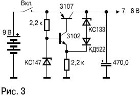
The device must be powered from a stabilized source. The version of the stabilizer used by the author is shown in the figure on the left. You can use a stabilizer microcircuit KR142ENXX for 7-8V or a foreign analogue LMXX for the same voltage.
Setting up a metal detector
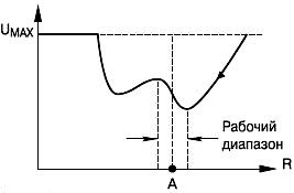
The generator is configured as follows. Instead of a constant resistor R1, a variable resistor with a resistance of 10 kOhm is installed, and the slider is brought to the position corresponding to the maximum resistance. With a decrease in its resistance, the voltage at point “A” will also decrease, as shown in the figure. At some point, it will stop decreasing and begin to increase. It is necessary to fix the moment when the voltage at point “A” becomes minimum, measure the corresponding resistance of the variable resistor and be sure to replace it with a constant one with the same resistance.
The generator is located on a separate small board in close proximity to the coil. All parts of the generator must be precise. The transistor can be of almost any p – n – p structure, even germanium with low gain. It will be desirable to select capacitor C1 with a capacitance in the range of 5–20 nF according to the maximum sensitivity of the circuit. Sometimes a good result happens when C1 is connected not to winding II, which is the base, but to the common wire. The coil of the loop has a diameter of 14-16 mm, 260 turns of wire with a diameter of 0.2-0.5 mm are wound on it with a branch from the one hundred and sixtieth turn.
A coil frame made of three corrugated cardboard circles turns out to be very simple and quite rigid. The middle circle should be slightly smaller in diameter than the outer ones. In addition to rigidity, corrugated cardboard has good thermal insulation properties, which can be used to increase the stability of the device. So, if the generator is assembled on chip elements, it can be easily placed between layers of cardboard, which will drastically reduce the impact on it of temperature drops and changes. It is not necessary to shield or insulate the rest of the device.
PCB drawing and arrangement of elements
Below are several options for a printed circuit board drawing for a metal detector and a photo of a finished soldered circuit.
As a basis – one-sided foil fiberglass.


With repeated repetitions of the circuit, the characteristics of this metal detector are fully consistent with the declared ones, if the sensitivity is increased to a maximum of 2 rubles to 20 cm. The coil contains 180 turns of wire 0.35-0.5. Branch from 80 turns to the base. The operating frequency of the metal detector is around 12 kHz. For the experiments, the second coil in the form of a rectangle 12 cm by 24 cm was also assembled. The results are the same as with the round one – the target is clearly identified in the center. In the assembled and folded form, the bar was made like this, for different metal detectors one universal, I also attach the blocks to the handle and ears on the coil the same.
Advice 1. When assembling a simple metal detector, we recommend that you install precision parts in the generator, especially regarding the feedback capacitor – 15 nF. A piezoelectric element is used as a sound emitter of the metal detector. To whom the volume is not enough, it is possible to make a separate bass amplifier, but it should be borne in mind that the current consumption will increase.
Advice 2. If there is a weak sensitivity of the device, then you may have to select the transistor for the maximum sensitivity, put BC557, KT3107 and similar ones with the maximum gain – everything works. The op-amp chip is replaceable with LM324, TL074CN or K1401UD2.
Advice 3. In the fully assembled coil, leave access to the adjustable resistor (in the emitter of the generator transistor) for every fireman – one coil had to be disassembled, after filling and drying the operating range went away. We are satisfied with the results of tests in real conditions, an excellent device for beginner metalworkers, the size of the target and the depth of the metal are well determined by the change in the tone of the sound.
The only and main disadvantage of the scheme is that there is no definition of the type of metal ( <), but considering only one regulator and economical current consumption (batteries of the “Krona” type are enough for about a week), this is an excellent circuit of a simple metal detector for novice radio amateurs!


