If you want to work with the AVR micro-controllers, you have to get a programmer. This article describes the simplest ISP programmer for AVR microcontrollers that works with a convenient program for flashing UniProf controllers (AVR serial Programmer).
This programmer is referenced to page: Link
The version PCB layout of the programmer under SMD components is attached.

On the developer’s site you can see the schematic diagram of the programmer.

For the manufacture of the programmer, we need the following components:
• 3 1N4148 diodes
• 7 1 kΩ resistors (1206)
• 1 resistor per 1 kΩ (1206)
• 3 0 kΩ resistors (1206)
• BD-9 connector (female)
• 3mm LED
• comb 2.54
• ISP connector (10 pin)
We strongly recommend to start the unpacking of the board with SMD components.
It should be noted that the board is divorced in such a way that most of the tracks go under the SMD components, which simplifies the soldering.

Next step, mount the remaining parts.

When washing the flux, the black flat on the diodes were erased. We look at the circuit diagram and assemble it in the right direction.
%%%%%%%%%%%%%%%%%%%%%%%%%%
Connecting the programmer to the microcontroller
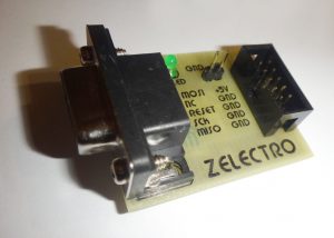
The programmer has a 10 pin ISP connector

Pin assignment of the ISP connector:
1 – MOSI (data output for sequential programming)
2 – VCC + 5V (Output + 5V, for powering a programmable board from a USB bus with up to * 200mA !!!)
3 – NC (Not connected)
4 – GROUND (common or minus power )
5 – RESET (Connects to the RESET pin of the microcontroller)
6 – GROUND (Common or minus power)
7 – SCK (Data clocking output)
8 – GROUND (Common or minus power)
9 – MISO (Data input for sequential programming)
10 – GROUND (Common or minus power)
The Gromov programmer supports AVR microcontrollers with ISP (In System Programming) serial programming mode , which the micro-controllers have an SPI (Serial Peripheral Interface) port .
Open the datasheet on the micro-controller (Atmega8), and we look for the section Pin configurations, in which we look at what legs the SPI port is represented

As we can see, these legs are the programming pins which numbered 1, 7, 8, 17, 18, 19, 20, 22, and they need to be connected to the corresponding pins of the programmer.
If a firmware has already been filled into the micro-controller and Fuses bits have been set to work from external quartz, then the quartz of the required nominal value should be soldered to the legs XTAIL1 and XTAIL2, and run through non-polar capacitors of 18-22 picofarad to ground.

If the programmer does not have a + 5V power supply you need to power the controller from an external source. There are 2 pins on the programmer board for power. For such purposes, it’s easier once and for all to use this cable:


It should be noted that the programmer also supports the AVRdude console program .
An example of downloading firmware to the controller can be seen on the example of filling the Arduino Bootloader he .
Original articles on this topic can be found at http://zelectro.cc/DIY_Gromov_Programmer
A full review of the UniProf program can also be found at http://www.getchip.net

The archive contains a template for LUT and a list of parts in Word format.
Open image => Print => Full page
To facilitate the decoupling of SMD components on the back of the board, where there is no marking, I’ll give a picture.


