
Metal detector on Arduino Pro Mini
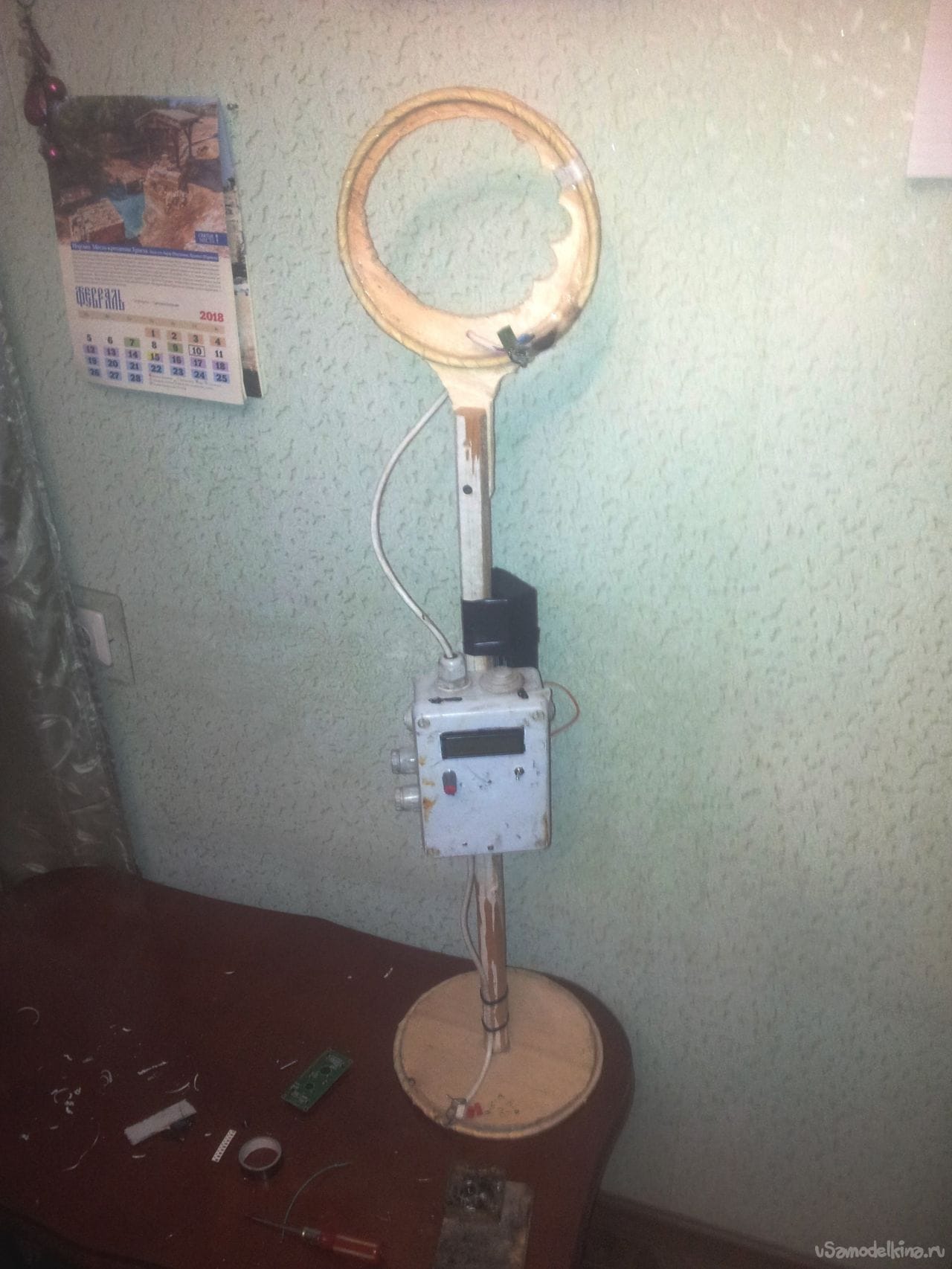
Reworking of the Kolokolov-Shchedrin deep-well scheme. Differences from the original circuit:
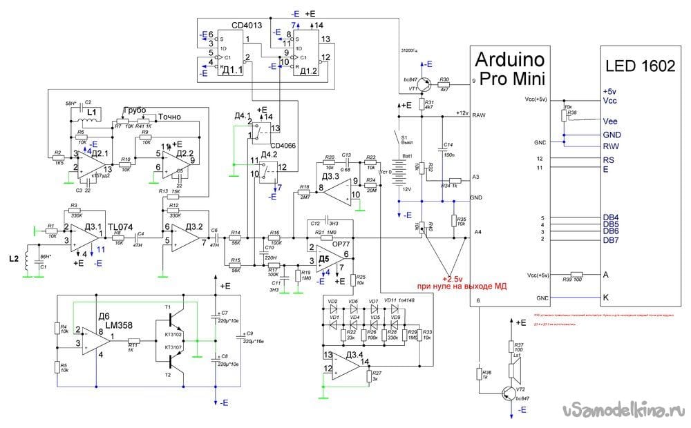
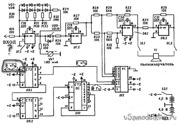
1. There is NO quartz oscillator on the k561 chip .. and quartz at 32 kHz. The 32 kHz signal is given by the Arduino Pro Mini.
2. Sound notification circuits on several microcircuits of the 561 series are also not present – Arduino also voices targets (And I must say it sounds excellent, compared to the author’s circuit).
3. Powered by unipolar voltage 12v (lead battery).
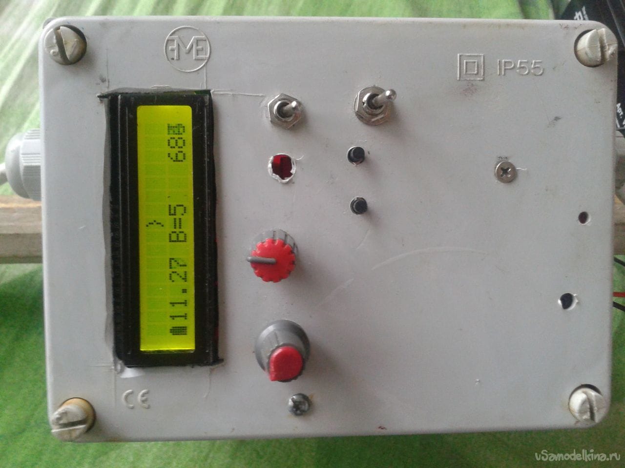
4. Sensitivity adjustment with buttons. With the ADC scale from 0 to 1023, the response threshold is adjustable from 1 to 38 (the value can be easily changed in the sketch).
THEMATIC TOOLS AND MATERIALS:
The most important thing that I wanted to show in this article is that it is possible to assemble an MD on Arduino that is not inferior to the original in sensitivity (it turned out, because about 10 pieces of the original circuit were collected, so there is material for comparison). Original scheme:
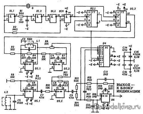
When I first started working with Arduino, I was so excited that I thought that I could find and assemble any Metal Detector circuit from the Internet on Arduino, which I could easily find in the open spaces of a large garbage dump. In principle, it turned out that way, but the schemes were based on a frequency meter, which did not allow to achieve a really good range. Some children’s toys and a test of the pen + attempts to make money on beginners. The original of this MD is a real workhorse that allows you to find large objects at a distance of 2m (see the book of Kolokolov-Shchedrin in Google). There are no statistics on the transformed MD. I hope it will appear with the support of MD and Arduino fans. The circuit worked with Arduino Uno and Arduino Pro Mini.
Further on the link, the process of the birth of this MD on the Soldering Iron website is laid out, which lasted more than one year and prompted the author to study duin programming. Perhaps the sketch will seem miserable to someone – I will gladly accept your CORRECTIONS.
At the moment, there is a sketch that allows you to adjust the sensitivity barrier (pin 7 duins +1 to the barrier, pin 8 -1 to the barrier). .
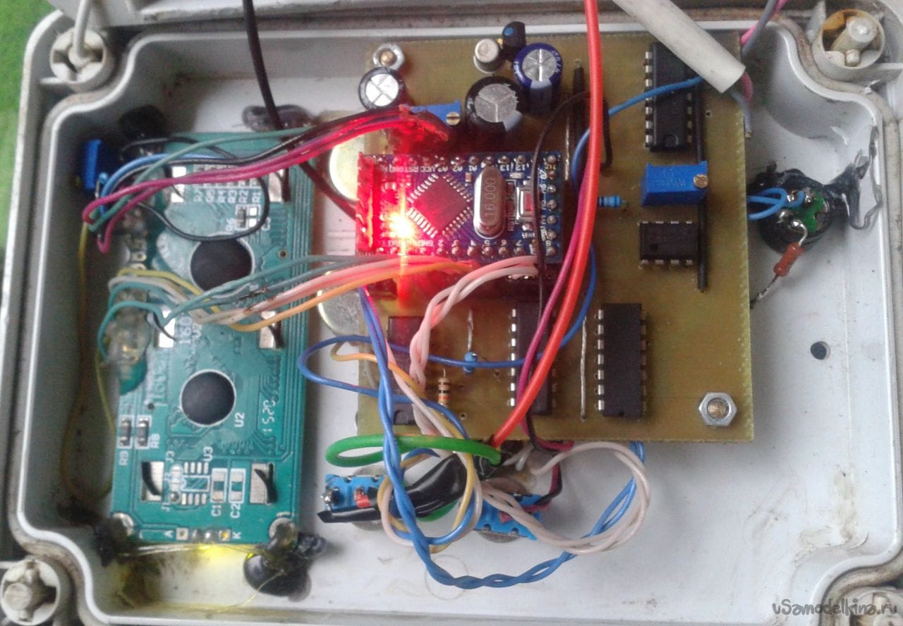
Arduino pro mini 5v, 16MHz, ATmega168 and the display used these. Next to the scale adapter Mini SD-
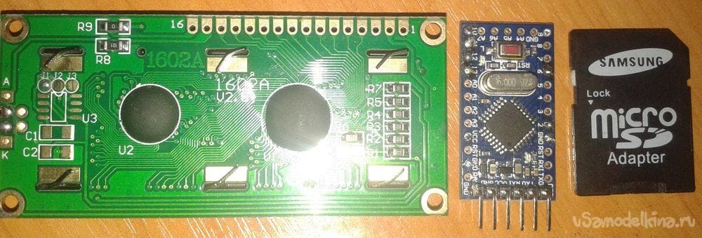
As already mentioned, 1602 costs 86 rubles, ProMini – 82 rubles. If you wish, you can generally take a naked ATmega168, develop a board for it and upload the sketch directly into it. And so, for example, I installed using the mom-dad connector on the MD board. The photo shows the Arduino has a 6-pin plug – through it, sketches were poured directly on the board.
Sketch-MD.Rx-Tx.ProMini.SrednjajaTochkaRegBar.ino
// A3-аналоговый вход для вольтметра
// А4-аналоговый вход для сигнала
// 6- вывод зука
// 9 - вывод частоты 31200 Гц
#include
LiquidCrystal lcd(12, 11, 5, 4, 3, 2);
byte z1[8] = { // значок батарейки
0b01100, 0b11110, 0b11110, 0b11110, 0b11110, 0b11110, 0b11110 };
int countleds = 0; // переменная для хранения значения уровня шкалы
int voltag = 0; //переменная для хранения значения напряжения
int noll = 0; //переменная для хранения значения средней точки
#define NUM_SAMPLES 10 // 10 аналоговых выборок для чтения за 1сек
int sum = 0; // сумма взятых образцов
int sun = 0; // то же, но деленное на 10
unsigned char sample_count = 0; // текущий номер выборки с
float voltage = 0.0; // расчитаное напряжение
const int button1 = 7; // кнопка барьер-плюс
const int button2 = 8; // кнопка барьер-минус
int i =5; // барьер
void setup(){
lcd.begin(16, 2); // инициализация дисплея
lcd.setCursor(1, 0);
lcd.print("CXEM.NET");
lcd.setCursor(10, 1);
lcd.print("Rx-Tx");
delay(3000);
lcd.clear();
TCCR1A = TCCR1A & 0xe0 | 2;
TCCR1B = TCCR1B & 0xe0 | 0x09;
analogWrite(9 ,126); // на выводе 10 ШИМ=50% f=31200Гц
lcd.createChar(1, z1);
}
void loop() {
int buttonState1 = HIGH; // Состояние кнопки один
int buttonState2 = HIGH; // Состояние кнопки два
sample_count = 0; //сбрасываем контур кол-ва сложений
sum = 0; //сбрасываем сумму 10ти сложений
while (sample_count < NUM_SAMPLES) {
sum += analogRead(A4); // к сумме плюсуется очередное измерение
sample_count++; // к номеру измерения плюсуется единица
sun = sum/10;} // находим среднее значение из 10ти измерений
noll = analogRead (A3)/2; // средняя точка питания
float voltage = map(analogRead (A3),0,1023,0,1500)/100.0;
//Вольтметр, построенный на входе А3
if (sun >= noll + i) {countleds = map(sun, noll+i, noll*2 - 250, 9, 14);
// если полученный рез-т на 9-15 сегмент шкалы
tone(6, countleds*100);}
if (sun <= noll - i) {countleds = map(sun, 116, noll - i, 0, 7);
// если полученный рез-т на 0-7 сегмент шкалы
tone(6, countleds*50); }
if (sun < noll && sun >=noll - (i-1)) {countleds = 7 ;
noTone(6); } //островок виртуального НУЛЯ(7 сегмент)
if (sun > noll && sun <= noll + (i-1)) {countleds = 8 ;
noTone(6); } //островок виртуального НУЛЯ шкалы(8 сегмент)
{lcd.setCursor(countleds, 0); // устанавливаем курсор в колонку countleds, строку 0
lcd.print("xff"); // закрашенный значок
lcd.setCursor(0, 1); // перемещаем во 2 строку, столбец-0
lcd.print(char(1)); // Индикация значка батарейки
lcd.setCursor(1, 1); // перемещаем на указание напряжения
lcd.print(voltage); // вольтаж
lcd.setCursor(7, 0); // 8й столбец 1я строка
if (sun < noll ) { lcd.print("{");} // печать
lcd.setCursor(8, 0); // 9й столбец 1я строка
if (sun > noll ) { lcd.print("}");} // печать
lcd.setCursor(7, 1);
lcd.print("B=");
lcd.setCursor(9, 1); // 11 столбец 2я строка
lcd.print(i); // барьер
lcd.setCursor(13, 1); // 13й столбец 2я строка
lcd.print(sun); // печать усредненного значения значения АЦП
delay(100); // ждём
buttonState1 = digitalRead(button1); // Чтение состояния кнопки 1
buttonState2 = digitalRead(button2); // Чтение состояния кнопки 2
if (buttonState1 == LOW) { i =i + 1 ; delay(50);}
// При нажатой кнопке барьер вырастает на 1. Задержка 50
if (buttonState2 == LOW) { i =i - 1 ; delay(50);}
// При нажатой кнопке барьер снижается на 1. Задержка 50
if (i < 1) { i = 1;} // Нижняя граница барьера
if (i > 38) {i = 38;} // Верхняя граница барьера
lcd.clear();
}
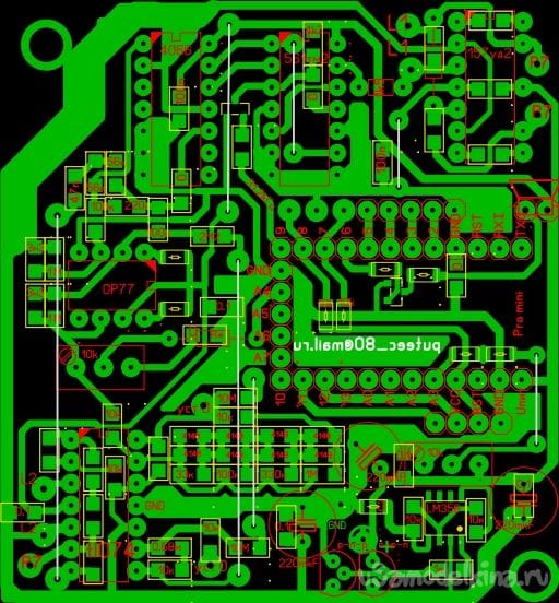
}I did not use autozero. The last two elements of TL074 were left idle. But on the diagram and the board they are. You may want to bring them to working condition a little later. I think I have achieved my goal. The display unit works great. Everything else depends on the MD.


