Pulsdetektor Minipuls-3
Minipuls-3 is the highlight of the Minipuls series. This detector is analog/digital hermaphrodite. However, it can be expanded to digital 10-bit signal processing with extended software and a minimal board change. An AT90S4433 takes over the pulse, touch and display control.
The display is via a 16×2 LCD in 4-bit mode. The average supply voltage is 12V/DC.
Depending on the power setting (Power), the current requirement is 120 – 300 mA. I already had an LCD with lighting included here with a series resistor of 47 ohms for the LED. Minipuls-3 also has a range controller. Depending on the operating conditions, this controller can compensate for ferromagnetic soils, limit the object size or provide help with pointing
The two trimmers only serve to set the battery voltage and the LCD contrast. Like Minipuls-1/2, Minipuls-3 is based on P-Mos technology. In my opinion, this technique is the easier way for the beginner.
Since the Minipuls-3 circuitry corresponds to the Minipuls-2/1, the data are also similar.
Technical specifications
- Operating voltage : 10 – 14V/Dc
- Operating current (3Ohm) : 110 – 300 mA
- Frequency : 500Hz Pulse duration : 75 – 320yS
- Primary current (3 ohms) : 1.2 – 2.2 A
- Secondary Peak : 400Vpk/2ys
- Max. Battery : Nc/Ni-MH
- Battery capacity (min) : 500mA
- Range (3Ohm/280mm) : 1.8 m (object dependent)
This data was measured on the sample with 12V/500mA Nc battery.


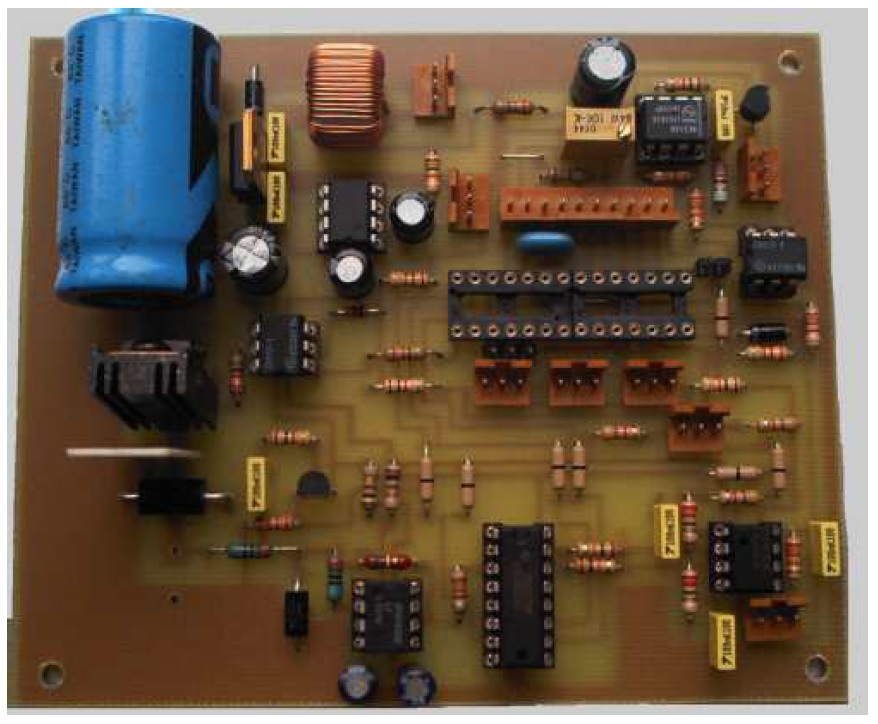
Circuit
The circuit consists of the following main components:
- Voltage control part U1 + U9
- Pulse part U11 + Q1
- Amplifier and sampler U3 + U4 + U5
- Integrator and amplifier U8
- Tone generator U6 + U7
- Control U12 + Lcd 16×2
The operating voltage is applied via X1/ L1. The task of L1 is to compensate for the inrush current of C1. C1 represents a short circuit for the battery when it is switched on and practically reduces the current to the internal resistance of the battery. This can also interfere with the PowerOn reset of the processor. This is avoided by the lagging current of L1. D1 takes the negative voltage spikes caused by the secondary field from the power supply. Since a hard-wired battery is provided, there is no additional polarity reversal diode in the input. The diode would bring a voltage drop in addition to L1. The P-Mos Q1 is switched by U11 and drives the coil. The suppressor diode D3 limits the peak to 400V. R1 dampens the coil. The pulse width and thus the power (power) is set with R53. Since the coil is an inductor, we are dealing with a lagging current. The longer the coil current is present across Q1, the more it increases. This process lasts until the coil loses its inductive part. Then we are dealing with a DC circuit consisting of the internal resistance of the voltage source – drain/source resistance of the P-Mo and DC resistance of the coil. The maximum pulse width must always be smaller than this saturation point. We can call everything that goes beyond that a heating mat. In addition, the range and sensitivity decrease drastically.
The measurement signal is fed to the operational amplifier U3 via R5/D4. At the same time, the peak-dependent sync signal for the processor (U12) is obtained from Q2. According to the programming, U12 feeds key pulses to the multiplexer U4. The sampled measurement signals are fed to the integrator U8-1 by U4 and amplified by U8-2. The amplification (gain) can be varied with R51. The amplified signal is fed to the tone generator (VCO) consisting of U6/U7 via R40. The threshold value or operating point of the tone generator is determined by the potentiometer R50.
The signal for U12-ADC5 is tapped at R39. The processor digitizes the measured value and displays it on the 1st line of the LCD as a bar graph and on the second line (right) as a numerical value 0 – 1000. The Potis Range and Power are immediately sent to the processor A/D supplied to converters. The acquisition time for a change is about 5 seconds. With regard to the measuring rate, a conversion is carried out here every 5 seconds.
The free port PC2/ADC2 (X9) is not operated in the software. This is for the fully digital signal processing mentioned. Here the gain potentiometer is replaced by a stereo potentiometer and informs the software of the current gain.
In anticipation that I find time to expand the software, whoever wants to install the stereo pot. A 7805 is installed in the power supply instead of the 78L05 so that an LCD with lighting can be installed.
The trimmer R44 battery voltage is to be set as follows: Please only place the processor in the socket after setting. Don’t worry, nothing can happen because the zener diode D2 limits the voltage divider to 4.7 volts. Switch on the charged battery and measure at U12 Port C4 Pin27. Trim to 1.2 volts (cell voltage) for NC battery and set to 1.25 volts for Ni-MH. That’s it. Set contrast trimmer R49 to ‘What are you looking at’.
If you want to install a fuse, you should definitely use an automotive fuse. These are low-voltage fuses as you know them from cars.
Operation manual


After this procedure, the LCD shows the operation picture. The battery is queried every 5 seconds, as are the setting controls ‘Power’ and ‘Range’. the processor switches off the pulse when the battery is empty and shows the ‘Please charge’ text.
Range:
The Range slider shifts the entire sample frame in the secondary field. This gives you the option of hiding smaller objects or compensating for electrical floor loads. There is also the possibility, without adjusting other parameters, to level the object when locating in such a way that a variable signal curve results for pointing. The function can be tested very easily. Range to middle position. Approach an object so far that about half the modulation results. If the controller is now turned to the left (in my case like this) the display will go to full display after 5 seconds. Analogously to the right to zero. You will get used to this function very quickly.
Power:
The pulse duration is determined with the Power controller. With this we change the search depth or search performance. see description at the beginning of this manual.
Gain
With the knob Gain the amplification of the measuring amplifier is determined.
threshold
The trigger point of the tone generator is determined with the Threshold controller.
Audio
With the audio controller we determine the volume. The audio controller is not mentioned in the schematic. It is switched in series with the loudspeaker, headphones. As a rule, a value of 1KOhm is sufficient for 32 ohms.
Parts List:

C16/17 typically 22pF-33pF
for crystal Quartz, oscillator for AT90S4433/ 8MHz,
LCD 16×2
Poti audio is in series with speaker 1K should be in each Insert case when headphone has no volume control. Jack socket with switch if required. BNC socket/plug
Assembly plan


Coil design
Minipuls works with any coil or coil shape.
The DC resistance of the coil should be in the range of 3 ohms. Just measure with a multimeter. If the coil is used in the online description, it should be pointed out again:
The two coils must be connected in series. Beginning – end, beginning – end in the winding direction.
The wire used is LIY 0.25 mm2 (tinned).
When using this wire, the large coil with a diameter of approx. 280 mm consists of approx. 30 turns and the small coil with a diameter of 120 mm consists of 20 turns.
The coil can of course also be used as a single coil !! diameter with enameled copper wire 0.6mm – 0.8mm diameter.
If the coil is not cast or foamed, it must be tied in a mechanically stable manner.
A coaxial cable, e.g. RG58U, is recommended as the supply line. The maximum cable length should not exceed 2.5m.
If you need a hand-held probe, you should choose a diameter of 120mm and an enamelled copper wire with a diameter of 0.4mm.
To dampen the decay process, solder a second resistor R1 over the coil.
More information about the coils will appear on the website soon.


