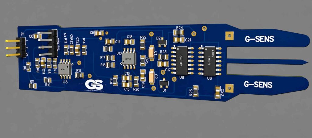
The FLC100 magnetic sensor has become a ubiquitous staple in both the hobbyist and professional detection worlds. To the casual observer, it’s just a simple green circuit board—a collection of surface-mount components that somehow translates the invisible pull of the Earth into precise data. But how does this humble arrangement of silicon and copper perform such a high-stakes task? By performing a “surgical” analysis of its schematic, we can uncover the brilliant engineering hacks that make it a masterpiece of efficiency, while revealing the fragile design choices that often lead to its failure in the field.
1. The “Parallel Power” Hack
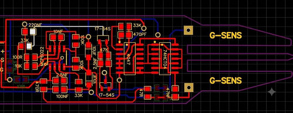
The first secret lies in how the designer handled the 74HC04 inverter. While these gates are typically used for simple signal logic, the FLC100 employs a clever power-delivery trick by linking pins 1, 3, 5, 9, 11, and 13 in parallel.
This isn’t a redundant design; it’s pure engineering muscle. The raw signal produced by the 4047 oscillator is fundamentally too weak to excite the sensor’s coil on its own. By bridging these pins, the designer increased the current capacity, providing the “muscle” necessary to trigger the magnetic excitation. This configuration highlights a specific intelligence: using standard, low-cost ICs to perform high-current tasks through parallel architecture.
Tech Spec: The Frequency Formula The heart of the FLC100’s rhythm is defined by its oscillator. Using a 33kΩ resistor (R) and a 470pF capacitor (C), the frequency (F) is calculated as: F = 1 / (R * C * 4.4) This results in a precise operating frequency of 14.7 kHz. Interestingly, while 14.7 kHz is the FLC100 standard, competing German, American, and Turkish manufacturers often shift this between 12 kHz and 17 kHz to give their hardware a unique “brand signature.”
2. The Carbon-Free Core & The “Resonance” Secret
If the circuit is the brain, the carbon-free metal core is the sensor’s heart. This component plays the single largest role in target sensing, but its effectiveness depends entirely on mechanical precision. For maximum sensitivity, the core must be perfectly straight, exactly the same length as the coil, and firmly attached to the coil mold rather than sitting “loose.”

The real magic happens via Series Resonance. By pairing the coil with a 47nF capacitor, the designer created a resonant circuit that transforms the “harsh” square wave of the oscillator into a smoother, more efficient wave. This wave drives the core into “Magnetic Saturation.” The sensor doesn’t just “see” a target; it measures a temporal fingerprint. When an external magnetic field (a metal object or a void) is present, the core reaches saturation faster in one direction than the other. The FLC100 measures this minute time difference to identify what lies beneath the soil.
“The carbon-free metal core plays the largest role in sensing targets.”
3. Diodes as Synchronous “Gating” Switches
The BAT54S Schottky diodes are the FLC100’s gatekeepers. They are not acting as simple rectifiers; they function as high-speed precision switches synchronized perfectly with the 4047 oscillator.
The signal returning from the coil is a messy “mixture” of the 14.7 kHz excitation current and the incredibly faint influence of the target. To extract the data, the diodes perform Synchronous Rectification. They “sample” or clip the signal at the exact moment the core reaches peak saturation—the moment when the external field’s influence is at its absolute maximum.
The Signal Transformation:
- Input: High-frequency AC signal (Excitation + Target data).
- Action: Synchronized peak-sampling via BAT54S diodes.
- Output: Stable DC voltage representing the external magnetic field’s intensity.
4. The Fatal “Magnet Test” Mistake
The most common way to kill an FLC100 is also the most intuitive: testing it with a strong magnet. Because the carbon-free core is designed for extreme sensitivity, a high-powered magnet can cause “permanent saturation.”
This “traps” magnetic flux in the core, resulting in “ghost targets” or a sensor that is permanently “blind.” To keep your sensor healthy, you should only calibrate using the Earth’s natural magnetic poles. A healthy, properly functioning FLC100 should yield the following precise voltage readings during a rotation test:
- Pointing North: ~3.3V
- Pointing South: ~2.0V – 2.1V
- Pointing East/West: ~2.7V
If your sensor is frozen at a fixed value regardless of orientation, it has likely been “magnetically poisoned.”
5. Why “SMD” Beats “DIP” for Precision
When it comes to high-sensitivity hardware, “Noise is the enemy of the amplifier.” The FLC100 relies on the MCP6022—an exceptional low-noise operational amplifier. In this high-gain environment, the physical footprint of the components matters.
Surface-Mount Devices (SMD) are vastly superior to Dual In-line Package (DIP) versions for this application. The shorter traces and smaller footprints of SMD components minimize the distance the signal travels, reducing the chance of picking up parasitic interference. This leads to a cleaner, more stable signal. While DIP components are easier for beginners to solder, they often introduce enough noise to mask the very “micro-volt” signals the MCP6022 is trying to amplify.
Conclusion: The Path from Student to Maker
Mastering the FLC100 is a journey of “errors and experience.” My own path began in 2020, knowing nothing about these circuits, and was forged through failed boards and careful observation. This sensor proves that you don’t need a degree in engineering to master the invisible; you simply need to understand the rhythm of resonance and the physics of saturation.
Now that you understand the secrets behind the FLC100’s heart, will you stick to the standard design, or are you ready to engineer your own magnetic signature?