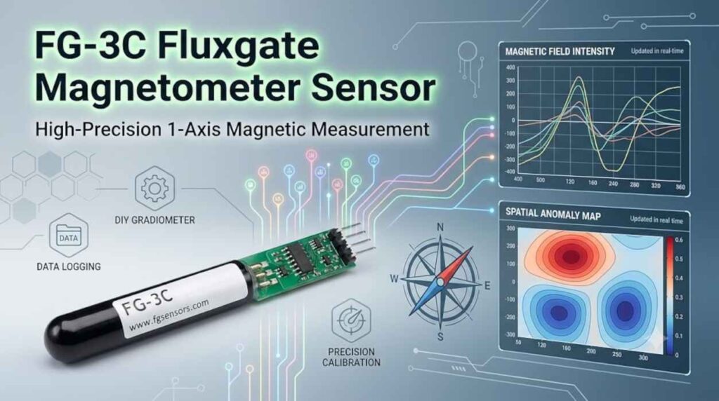
Golden Sensitivity 3D Ground Scanner

The term “Golden Sensitivity 3D Ground Scanner” refers to a class of advanced metal detection and subsurface imaging devices that use sophisticated magnetic field sensors to create three-dimensional visualizations of buried objects and underground structures. These scanners are specifically designed for treasure hunting, archaeological exploration, and locating deeply buried metallic objects, including gold and precious metals.
Core Technology
At the heart of these advanced ground scanners lies high-sensitivity magnetometer technology, particularly fluxgate sensors like the FLC100. These sensors detect minute variations in the Earth’s magnetic field caused by buried metallic objects or subsurface disturbances. Unlike conventional metal detectors that rely on induction coils alone, 3D ground scanners combine multiple sensing technologies:
- Magnetic field sensors (magnetometers) for detecting ferrous metals and large subsurface anomalies
- Inductive search coils for near-surface metal detection
- Ground penetrating radar (GPR) technology on premium models for depths up to 40 meters
How It Works
A 3D ground scanner operates by systematically walking across a search area in a grid pattern while the sensor records magnetic field data. The process typically involves:
- Scanning Path: The user walks in parallel lines across the survey area, with the sensor pointing vertically toward the ground. Measurements can be taken automatically or manually triggered at each point.
- Data Collection: The device records magnetic field intensity at each measurement point, building a dataset representing the subsurface magnetic signature.
- 3D Visualization: The collected data is transferred to dedicated software (such as Visualizer 3D Studio) that generates color-coded 3D representations showing the position, size, depth, and shape of buried objects.
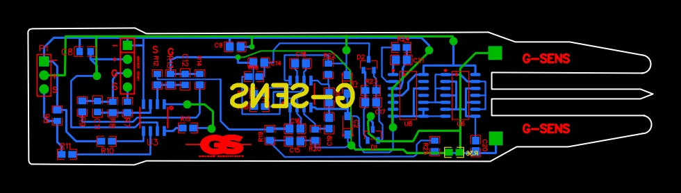
FLC100: Component Values & Part Labels
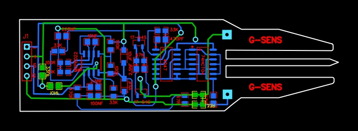
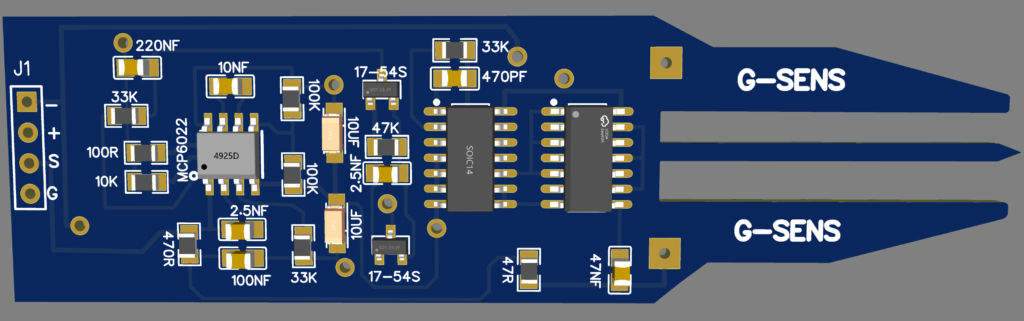
Here are all the component values and labels used in the PCB design of FLC100 sensor:
| Connectors & Headers | J1 | 4-pin main header (-, +, S, G) |
| Integrated Circuits | MCP6022 | Dual Op-Amp (SOIC-8 package, left side) |
4047 | Monostable/Astable Multivibrator (DIP/SOIC-14) | |
74HCT04 | Hex Inverter IC (DIP/SOIC-14) | |
| Transistors / Diodes | 17-54S | Transistor/Diode pair (SOT-23 package, 2 units) |
| Resistors | 100R | Resistor near input/MCP6022 |
10K | Resistor near input | |
470R | Resistor bottom-left | |
33K | Multiple positions (top-left, bottom, top-right, bottom-right) | |
100K | Resistors near center signal path (2 units) | |
47K | Resistor near center | |
47R | Resistor near bottom right IC connections | |
| Capacitors | 220NF | Capacitors (top-left) |
10NF | Capacitors (top & bottom) | |
100NF | Capacitor (bottom-left) | |
2.5NF | Capacitors (bottom & center, 2 units) | |
10UF | Polarized/Electrolytic Capacitors (center, 2 units) | |
470PF | Capacitor (top right near ICs) | |
| Board Branding | G-SENS | Printed on probe tips (top & bottom) |
Comparator + FLC100 N°1
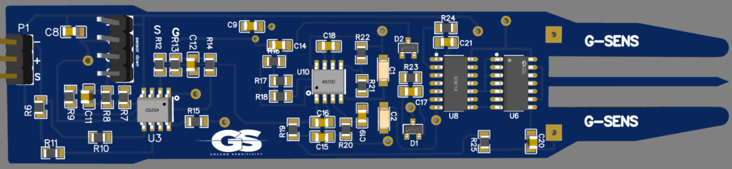
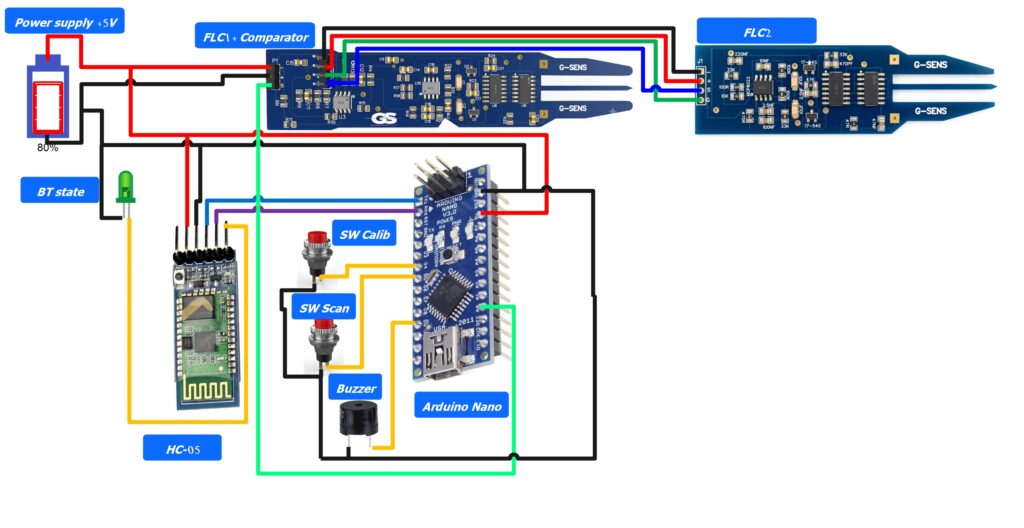
The overall diagram connection
Download files
This content is available to logged-in users only.
هذا المحتوى متاح فقط للمستخدمين المسجلين.
Ce contenu est réservé aux membres connectés.
🔑 Login 📝 RegisterLog in or create a free account to access downloads and exclusive content.