Metal detector AQUASOUND
The AQUASOUND metal detector is a device that selects metals and has the ability to phase-cut the earth (and salty sea water).
The scheme of the device is taken from the Internet (possibly old and with errors). This metal detector is quite popular in America and Florida in particular. There are many videos on YouTube on the topic of underwater searches with this device. By the way, this device, despite its apparent simplicity, costs quite a lot of money – from 1200 to 2000 or more US dollars.
Here is the diagram.

So, in order.
Let’s start with the power supply of the device.
Here is the power supply schematic.

Power supply of the device from 2 9 volt elements of the Kron type (9 + 9 = 18 Volts).
In the circuit, there is immediately a diode bridge for charging the batteries of the device, and an LED for signaling the presence of charging voltage. The LED and the resistor in its circuit are also current-setting elements that limit the charging current.
At the beginning, when the batteries are “fully discharged”, we have the maximum voltage and current from the charger, and of course the LED is lit brightly.
Gradually, the batteries are charged, the voltage on them increases and the difference (“shoulders”) between the incoming voltage from the charger and the voltage from partially charged batteries decreases, and the LED lights up more dimmerly.
With the right voltage for the charger, you can get almost complete “fading” of the LED and stop the charging process. Such a charging machine …
Further, according to the power supply circuit of the device (diagram above).
From +18 volts (Battery) – there is a tap for powering the audio frequency amplifier stage (sound to headphones).
Further, 18 volts from the battery pass through the power regulator, made on 78L12. The 12 volt output is fed to the main part of the circuit.
Further, through the transistor 2N2222, two resistors, an electrolytic capacitor with a capacity of 470 microfarads, a certain midpoint of the power supply circuit is formed – we have an output of +5 Volts. The +5 Volt pin is used as the reference voltage for the op amps in the circuit.
And so the device circuit works from 4 power points:
– circuit ground – battery power minus;
– +18 Volts (Battery);
– +12 Volts;
– + 5 Volts.
Instrument generator, sensor balancing device.
It is worth starting with the fact that the generator of this metal detector, and indeed the entire design of this unit, is taken from the US patent US4099116.
Cascade diagram (generator and phase balancing), see below.

The upper transistor in the circuit is a generator power amplifier and has a regulator – “Power” (power).
Interesting is the winding of the Tx coil (L1) of the generator. Winding data, see below (after the description of the receiver). Due to the partial inclusion of the transistor in the circuit, the generation of a given frequency is easy and stable. Let’s take a closer look at the L1 (Tx) coil. It consists of 4 sections that participate in the general generation process (as a single coil), at the same time, 2 of them are needed for further phase-amplitude correction of the Rx signal. Sections with terminals 1-2-3 are generating (positive phase), section with terminals 3-4-5 is compensating (negative phase).
Removing the signal for balancing Rx (L2) “to zero” is carried out from pin 2 (+ phase) and pin 4 (minus phase). The amplitude (voltage) of the Rx coil signal is regulated by the minimum at the input to the receiver, as well as its small compensation from the influence of the soil (phase correction). This can be done with two “NULL” potentiometers (nominal 100 kOhm each).
All the elegance of this solution is to pick up signals for balancing Rx (L2) directly from the generator coil Tx (L1) and not introduce an additional electronic circuit for this. The payoff for this is a cable with 7 wires, which is not always convenient.
Synchrodetector Reference Signal Conditioner
The diagram of the cascade for generating the reference signal of the sync detector with phase control – “Marine Balance”, see the figure below.

From the generator of the metal detector (from the collector of the transistor 2N2222), the reference signal is taken and then, using two cascades on transistors (2N2222) and a phase controller – “ Marine Balan with e ” (potentiometer 20 kOhm), we send a signal to the LM393 comparator. Further, through the RC circuit, and the transistor outputs a “digestible” signal of the desired phase to the sync detector (transistor 2N5484). The phase for sea water and sea soil (under water) is in a negative value (sometimes up to -75 degrees).
Take-up Coil and Receiver
The figure below is a cascade diagram.

The receiving coil Rx (L2) has 3 outputs (output from the middle).
Signals for balancing the receiving coil Rx in amplitude and phase come from the NULL potentiometers and further according to the scheme: one with a resistance of 150 kOhm (pin 1 of the L2 coil); the second with a capacitor of 30 picofarads (pin 3 coil L2), respectively.
The signal from the receiving coil L2 (pin 2), through a decoupling capacitor with a capacity of 0.1 uF, is fed to the base of the bipolar npn transistor 2N2222.
Further, according to the scheme, the signal is amplified by transistors and fed through the “search / set” switch to the sync detector.
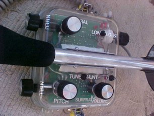
Separately, I would like to say about the search / set switch (literal translation sounds like search / set-installation).
In the “SEARCH” mode, of course, we are searching for targets ourselves. But here the device is configured by turning the toggle switch to the “SET” position. By turning the “NULL” knobs, we bring the search sensor into operation: this setting is done by ear, according to the minimum signal in the headphones, for which we first unscrew the “TUNE” knob (setting, tone) to a position in which there will be a constant sound tone in the headphones .
Below is a table of winding data for the AQUASOUND metal detector search probe for operation at frequencies of 20 and 40 kHz.

Main unit
Here is the cascade diagram.

The signal from the Rx coil, after pre-amplification, comes to a sync detector, which is a 2N5484 field effect transistor. The reference signal “marine balance” comes from the already agreed block. Next, the signal enters the capacitor 10n, connected between the ground and the output of the sync detector. In the absence of a metal target in the field of the search sensor, the signal from the soil and water is too weak, and the capacitor is charged by a value much less than the reference voltage of the operational amplifier (+5 Volts). When a useful signal from the target appears, the capacitor is charged by a voltage value higher than the reference voltage.
Further, the signal from the 10 nanofarad capacitor, passing the cascade to the LM358 through a non-inverted input (leg 3), enters:
- to the next stage of the operational amplifier (hereinafter referred to as the op-amp) made on the LM358 chip.
- to the tracking and auto-correction circuit of the signal made on the operational amplifier CA3130.
Let’s analyze point 2 . For good operation of the cascade, such an interesting operational amplifier, the CA3130, was not in vain used. You read his datasheet. In this cascade, simple and affordable opamps are not suitable!
The “TUNE” knob (literally – tuning) regulates the threshold voltage that is supplied to the inverting input 3130 (2 legs). And already from its output (leg 6) a signal is formed opposite to that coming to the sync detector. That is, there is a mutual subtraction of signals or, in other words, compensation.
What does it give us and how does it work?
When the metal detector is set up and the search sensor is driven near the bottom (and you can’t move quickly under water …), then the signal from water and soil, as well as small debris and minerals, will make its changes to the receiving path, then it will increase and we will have an audio signal at the output, like a metal target. Let’s take water and soil as almost “homogeneous” interference, then they can be subtracted by this compensation cascade.
As soon as a metal target enters the zone of the search sensor, the signal from it will stand out sharply from the main one. The compensation cascade does not have time to work out this surge and the device will give an audible signal.
The TUNE control is also actively involved, both in the correction (balancing) of the search sensor, which we discussed earlier, and in setting the ground compensation threshold.
To compensate for the ground, after balancing the receiving coil, it is enough to move the search head near the bottom and tighten the “TUNE” control so that the device does not give out false signals.
All this happens by ear and therefore very convenient.
Now for point 1 (cascade on the second half of the LM358).
The signal from the target, having passed it, exits from leg 1 and enters the 1N914 diode. As soon as the signal (voltage) received by the diode exceeds the value and sign and can pass through the diode, then automatically this voltage will be modulated by the audio frequency and will go to the audio frequency amplifier and then to the headphones.
Sound generator and output stage.
Scheme.

So the sound generator in the device is implemented on one half of the LM393 comparator. The frequency of the sound generator is preliminarily set by RC chains, but within certain limits it is regulated by the PITCH potentiometer.
Audio frequency oscillations from foot 7 (LM393), through a resistance of 100 kOhm, are fed to the gate of the field-effect transistor 2N5484.
If there is a “useful signal voltage”, it will be passed through the field device with the sound frequency of the sound generator itself.
Further, voltage pulses with sound frequency through a 0.1 μF decoupling capacitor enter a low-frequency amplifier made on two transistors: 2N907 and 2N2222 (the load of which is the primary winding of a transformer with a resistance of 25 ohms).
The secondary winding of the transformer has a winding with a tap from the middle and the number of turns twice as large as the primary.
This solution was made for use as piezoelectric headphones. And in their work, for an acceptable volume, they need increased voltage.
Note:
Search sensor balance setting:
- Immerse the device in water for 5 minutes (so that the search sensor takes the temperature of the water at the search site);
- Switch the toggle to the set position .
- Turn the TUNE knob until a stable sound appears in the headphones;
- Turn the NULL knobs alternately until the signal in the headphones is minimized (as far as possible) – the first stage.
- Use the NULL controls to find a position at which the targets are clearly defined and the ground has little influence (sweeping the search sensor near the ground).
- Turn the TUNE knob smoothly until the sound disappears in the headphones (with the same swings near the ground).
- In case of poor performance, repeat the setup procedure (points 1-6).
I described the AQUASOUND metal detector and the operation of most of its components. I am sure that soon you will see here a continuation article about the revised author’s version of the device with changed nodes, the board and the resulting characteristics.
Good luck to everyone in assembling and searching for the AQUASOUND metal detector !