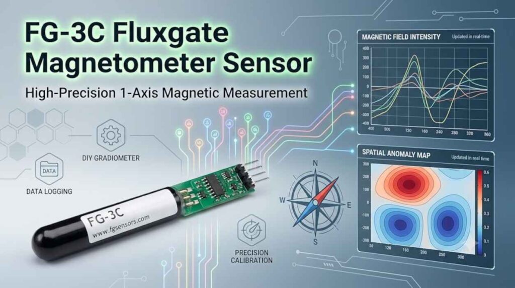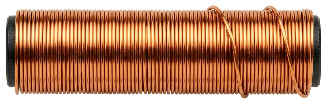
In the world of high-end hardware hacking, we often assume that precision components—like the specialized coils required for a FLC100 sensor—demand industrial-grade manufacturing. But if you’ve spent enough time at a cluttered workbench, you know that the most elegant solutions are often found in the scrap bin. The bottleneck for many DIY electromagnetic projects isn’t the budget; it’s the difficulty of winding a consistent, low-noise bobbin without a professional lathe. As it turns out, the “secret ingredient” to achieving professional-grade sensitivity isn’t a custom-machined part—it’s a plastic lollipop stick.
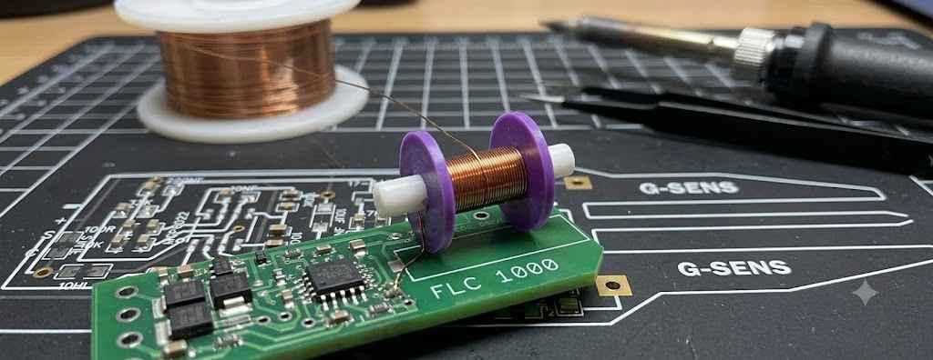
The Lollipop Bobbin: Engineering the Perfect Core
The foundation of any high-performance sensor is the bobbin. For a sensor like the FLC100, you need a core that is lightweight, perfectly cylindrical, and, most importantly, non-conductive. A standard plastic lollipop stick fits the bill perfectly. By using a “light shaft”—essentially a small mandrel or guide rod—to define the internal shape, you can ensure the bobbin remains structural during the winding process.
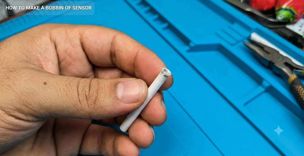
To prep the rig, cut the plastic stick to a precise length of two centimeters. I recommend marking your cut lines with a wax stick for high visibility against the plastic.
“first we will need a lollipop then we will cut off the plastic part like this…”
From a hardware hacker’s perspective, up-cycling this mundane plastic is a strategic choice, not just a budget one. Unlike metal cores, plastic is immune to eddy currents—circulating currents that would otherwise be induced within a conductive bobbin, creating heat and interfering with the sensor’s magnetic field. By using plastic, we preserve the “Golden Sensitivity” of the coil.
The Screwdriver Lathe: Precision Winding for the Modern Maker
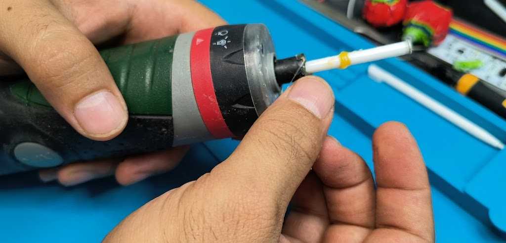
Hand-winding a coil is a recipe for disaster. Uneven tension and messy “lays” lead to stray capacitance, which can shift the resonant frequency of your sensor and ruin its accuracy. To get a professional, tight alignment, you need to rig a DIY lathe using an electric screwdriver.
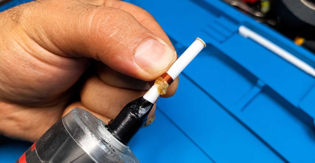
The trick here is securing the plastic bobbin to the tool. Forget the “health cells” mentioned in rough transcripts; what you’re actually doing is applying a bit of adhesive or wax to the screwdriver’s bit holder or chuck (the head of the tool) to lock the plastic piece in place. Once the adhesive sets, the winding process becomes “easy and smooth.”
Using a powered tool allows for constant tension and a perfect side-by-side wire lay. This mechanical consistency ensures that the electromagnetic properties are uniform across the entire length of the coil, preventing the parasitic resistance and signal noise that plague hand-wound components.
The Geometry of Copper: Navigating Wire Gauges
When it comes to the “meat” of the sensor, your choice of magnet wire is critical. While the standard build for the FLC100 utilizes 0.25mm diameter wire, there is room for experimentation.
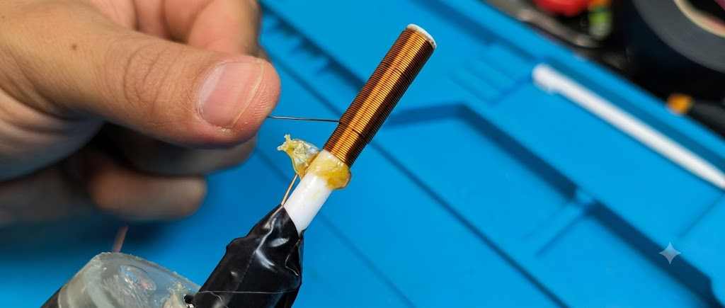
- Hacker’s Note: Using 0.15mm or 0.2mm wire allows for a much smaller physical footprint, which is great for tight housing constraints. However, be aware of the trade-off: thinner wire increases the DC resistance of the coil.
The goal is to continue the winding process until you hit the “appropriate inductance” for your specific circuit. It’s a balancing act between the physical volume of the coil and the target electrical properties required to make the sensor “sing.”
The Core Secret: Boosting Inductance without Resistance
The final “pro-move” in this build involves a bit of electromagnetic wizardry. Once the winding is complete, the inductance may still be a bit low for the FLC100’s requirements. You could add more wire, but that would increase the resistance (R), leading to signal loss and a lower Quality (Q) factor.
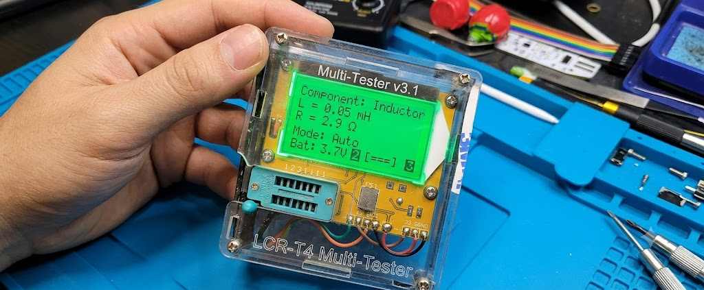
The solution is to insert a high-carbon ferromagnetic core (often referred to as “carbon 3” metal) into the center of the plastic bobbin.
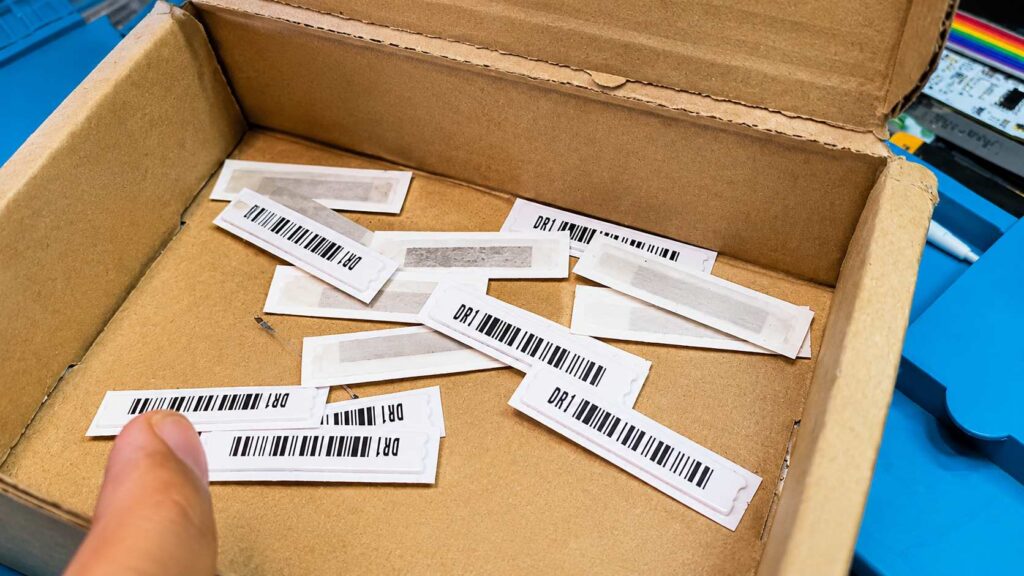
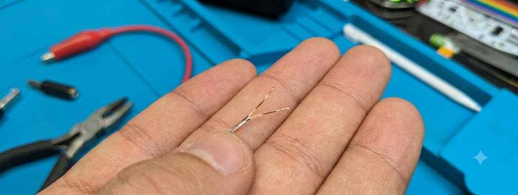
“I will insert this piece into the plastic in order to increase the inductance of the coil while maintaining the resistance.”
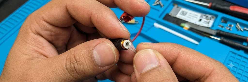
By introducing a core with high magnetic permeability, you significantly boost the inductance (L) because the metal concentrates the magnetic flux lines. Since the length of the copper wire remains the same, the resistance stays flat. This optimization gives you a high-gain, high-precision sensor without the thermal noise associated with longer wire runs.
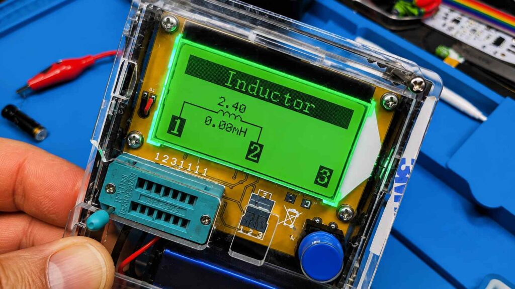
Conclusion: Calibrating for “Golden Sensitivity”
Once the core is seated, the build moves into the calibration phase. You must verify the final result using an “LC method”—utilizing an LCR meter or a frequency counter—to ensure the inductance perfectly matches the FLC100’s specifications. This final check is what separates a “toy” from a professional tool.
This project is a testament to the maker spirit: that with a lollipop stick, some copper, and a repurposed screwdriver, you can build hardware that rivals industrial sensors. It forces us to look at the world differently. What other everyday objects are hiding in your house, waiting to be the core of your next great invention?